Feedback diagnosis
ZX7-500A Current Feedback and Voltage Feedback Diagnosis
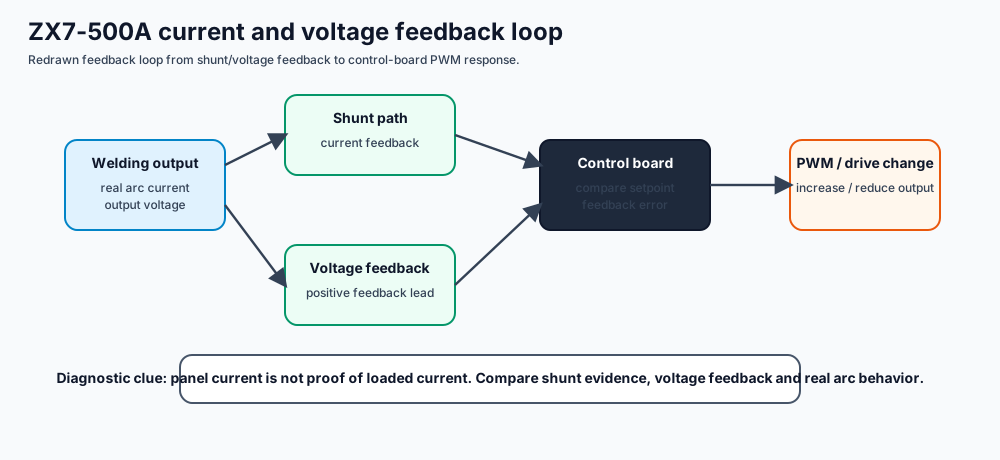
Separate real output current from display value, current feedback, voltage feedback and control-board response.
Quick Answer
Use this page when the welder output, display value, current feedback or voltage feedback do not agree with each other.
- Compare real loaded current, panel display and feedback signal before adjusting calibration.
- No OCV should be treated as a power-path fault first, not as a feedback calibration fault.
- Wrong display or unstable current often requires checking shunt, current feedback and voltage feedback together.
Use this page when
- Current display is wrong.
- Loaded current is weak or unstable.
- Feedback lines or shunt evidence are suspect.
Do not use this page when
- Input breaker trips immediately.
- IGBT or rectifier is shorted.
- The machine has no control power.
Feedback diagnosis goal
The goal is to determine whether the machine is actually producing output current, whether the shunt/current feedback reports it correctly, and whether voltage feedback agrees with output voltage.
Feedback fault table
| Observed symptom | Likely feedback layer | Diagnostic direction |
|---|---|---|
| Panel current changes but arc does not | command exists, output or feedback may fail | Check loaded current and output diode path before adjusting calibration. |
| OCV present but loaded current weak | output diode, reactor, shunt feedback | Compare OCV, welding load and shunt evidence. |
| Current display wrong | current feedback or display path | Measure feedback signal and compare with real current. |
| Voltage display wrong | voltage feedback open or noisy | Inspect feedback lead and return path. |
| Protection under load | feedback/protection conflict | Check current feedback, temperature relay and output short evidence. |