Calibration reference
ZX7-500A P1–P4 Calibration Points
A redrawn English reference for ZX7-500A P1, P2, P3 and P4 calibration clues.
Quick Answer
P1–P4 calibration should be used after power-path and feedback faults are isolated. Do not use calibration to hide a bad output diode, shunt, connector or control board.
- Confirm OCV and loaded current behavior first.
- Confirm current and voltage feedback paths before changing calibration points.
- Use P1–P4 as a validation layer, not as the first repair action.
Calibration should follow fault isolation
P1–P4 values are useful only after the high-energy path, output diode modules and feedback wiring are proven. Do not use calibration to hide a bad rectifier, shunt, connector or control board.
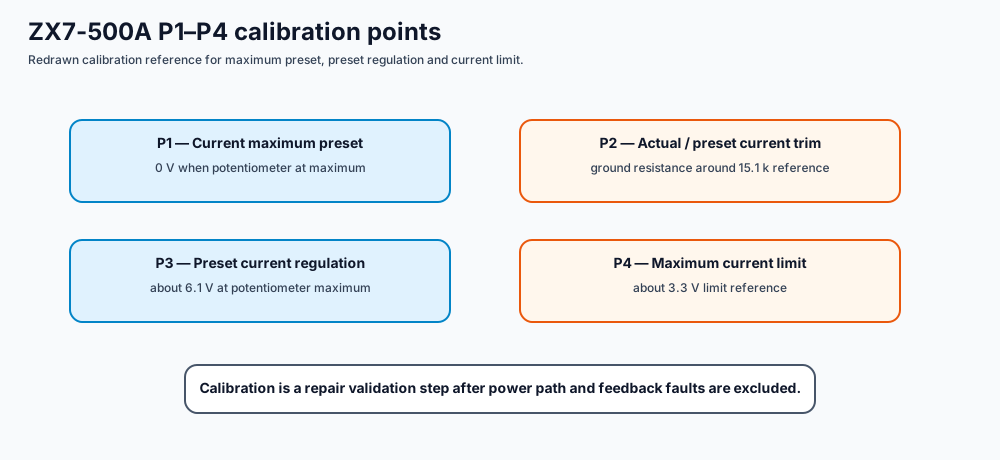
P1–P4 quick table
| Point | Meaning | Reference clue |
|---|---|---|
| P1 | current maximum preset | 0 V when potentiometer is at maximum. |
| P2 | actual welding current / preset current adjustment | used to align actual and preset current; source note references ground resistance around 15.1 k. |
| P3 | preset current regulation | about 6.1 V when potentiometer is at maximum. |
| P4 | maximum current limit | about 3.3 V limit reference. |
Use with caution
Calibration points belong to repair validation. If the machine has no OCV, trips the breaker, has a shorted output diode, or has missing feedback wiring, fix those faults before touching calibration.