Circuito
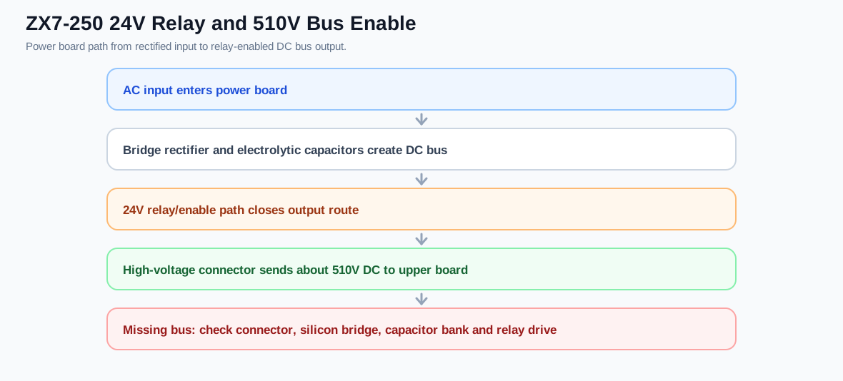
ZX7-250 24V relé y 510V DC Bus Enable Circuito
A circuit explanation para the ZX7-250 potencia-placa path that uses puente rectification, capacitor storage y relé enabling to deliver the alta tensión bus to the upper placa.
Circuit role
The 24V relé / DC-bus habilitación path controls whether the rectified y filtered alta tensión bus reaches the upper inverter placa. In a ZX7-250 sin salida repair, this path is important because the fan may run while the alta tensión bus is still missing at the connector feeding the inverter etapa. A technician should not move directly to PWM o driver diagnóstico until this potencia-placa salida path is confirmed.
Redrawn circuit path
Component functions
Puente rectificador
Converts the AC entrada into alta tensión DC. A short here can trip the breaker instantly; an open o damaged puente can prevent the bus from reaching the inverter placa.
Electrolytic capacitor bank
Stores the rectified bus DC. Bad capacitores can produce low, unstable o unsafe bus voltage.
24V relé
Routes o habilitacións the alta tensión salida path after the control condition is met. Bad contacts o missing coil drive can leave the upper placa without bus voltage.
Alta tensión connector
Carries the bus DC toward the upper inverter placa. Burnt pins o loose connectors can create sin salida fallas even when the potencia placa is otherwise alive.
Tabla de pruebas
| Test | Comportamiento esperado | Dirección de reparación |
|---|---|---|
| relé coil supply | relé receives its intended control voltage | Control supply, driver transistor o harness falla |
| relé contact | Low resistance when closed | Burnt relé contact o open salida path |
| Bus before relé | bus DC exists after puente/capacitor etapa | Bridge/capacitor falla if missing |
| Bus after relé / connector | About 510V DC in this diagnóstico path | relé/contact/connector path falla if missing |