Circuit
Inverter TIG Auxiliary Power and Protection Rails: 24V, 20V, 15V, Overvoltage, Undervoltage and Overheat
A WelderData rail and protection reference for TIG inverter control boards where fans or display may work while PWM remains disabled.
Database summary
This WelderData reference records a TIG inverter auxiliary-power and protection pattern using 24V, 20V and 15V rails. The rail names and thresholds should be treated as board-family references, not universal values for every clone, but the service logic is highly practical: a working fan or display does not prove that the driver rail, IC rail or protection path is healthy.
WelderData rail map
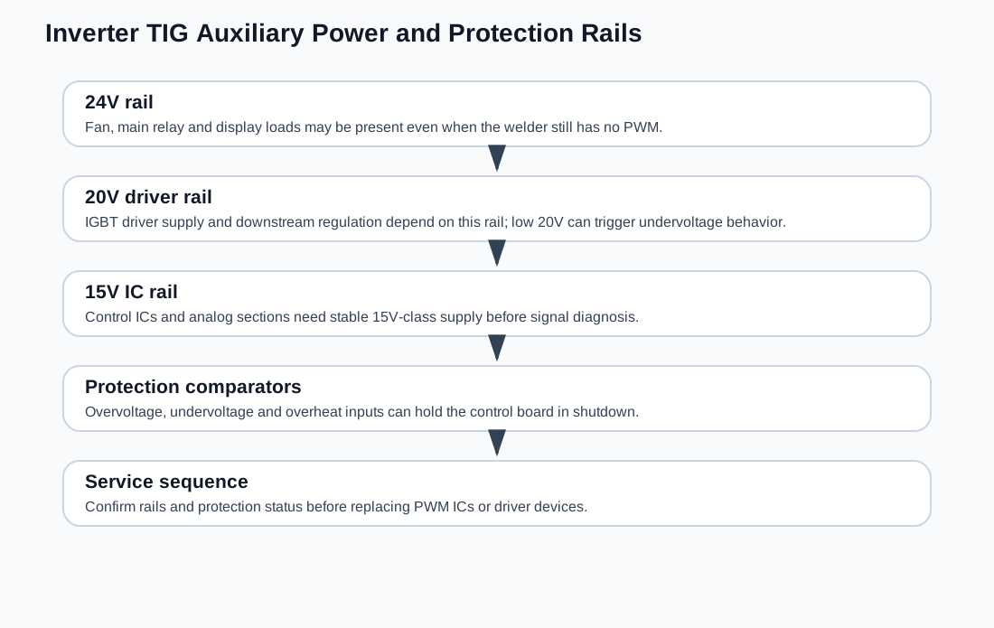
Rail functions
| Rail | Typical load | Repair meaning |
|---|---|---|
| 24V | Fan, main-circuit relay, digital display and auxiliary loads | Can be present while PWM remains disabled. |
| 20V | IGBT driver circuit and downstream regulation | A low 20V rail can create weak drive or undervoltage shutdown. |
| 15V | Control IC and analog control stages | Missing 15V can stop oscillator, comparator or PWM behavior. |
In service work, do not stop at the first visible sign of life. A fan running from 24V does not confirm that the 20V driver rail or 15V control rail is acceptable.
Protection thresholds
The training pattern behind this record includes three important protection ideas: mains overvoltage around a 260V class threshold, undervoltage behavior when the mains falls toward the 160V class range and a related driver/control rail drops too low, and thermal protection when the IGBT heatsink rises into a high-temperature condition around a 70°C class point.
These numbers should be used as practical routing references, not as universal trip points for every TIG inverter board. The important workflow is to check whether the control board is intentionally shutting down before replacing PWM or driver devices.
Repair routing
- Display works but no output: check 20V/15V rails and protection input state before replacing the PWM IC.
- Fan works but relay does not: check 24V distribution, relay coil path and control transistor.
- Protection light stays on: separate overvoltage, undervoltage and overheat inputs.
- Undervoltage symptom: check mains, transformer secondary, 20V rail and regulator stages.
- Overheat symptom when cold: check thermal switch wiring and comparator input before assuming the heatsink is actually hot.