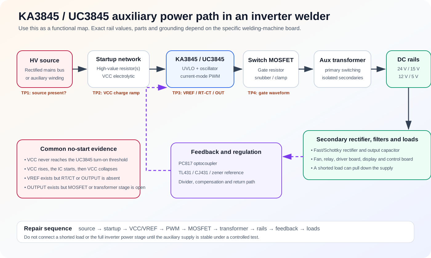
Use this circuit map to understand why a welder can have a healthy DC bus but no fan, display, relay or control power. Diagnose the path in sequence instead of replacing the PWM controller first.
Functional path of a welder auxiliary supply
The auxiliary converter turns the rectified mains bus or a dedicated auxiliary source into isolated low-voltage rails that wake the fan, relay, control board, gate drivers and display. A typical path is startup resistor → KA3843/KA3845/UC3845 → switching MOSFET → auxiliary transformer → secondary rectifiers and filters → 24 V/15 V/5 V loads → optocoupler feedback.
Original WelderData functional diagram. Exact rail names, transformer pins, grounding and component values depend on the board.
Startup resistor and auxiliary-winding handoff
At first power-up, a high-value resistor network charges the controller VCC capacitor from the high-voltage source. Once the controller starts switching, an auxiliary transformer winding normally supplies enough bias current to keep VCC above the turn-off region. A supply that starts then repeatedly stops often fails at this handoff rather than at the controller itself.
VCC never rises
Open startup path, leaky VCC capacitor, shorted VCC clamp or controller.
VCC rises and holds, no pulse
Reference, timing, current-sense or compensation problem.
Weak transformer/rectifier path or excessive downstream current.
Controller output, gate path and primary switching
The controller output does not directly prove that the transformer is receiving energy. Check the output pin, series gate resistor, any buffer transistor, MOSFET gate-source waveform, source-current resistor, snubber and transformer primary. A damaged gate resistor or shorted MOSFET can leave the controller apparently active while the secondary remains dead.
Scope reference: primary switching waveforms must be measured with an isolation-safe setup referenced to the documented primary return. Do not use secondary return or chassis earth as a substitute.
Secondary rails and downstream loads
Rail family
Typical uses
When absent
24 V class
Fan, relay, gas valve, wire-feed or control distribution.
Check winding, rectifier, filter, connector and external load.
15 V class
Analog control, current feedback, gate-driver or op-amp rails.
Check post-regulator stage and driver-board load.
12 V class
Relays, panel electronics or board-specific circuits.
Follow the exact schematic; not every board has this rail.
5 V class
Logic, MCU, display and sensor reference.
Check regulator input, output short and connector distribution.
Rail values are labels for common architectures, not universal acceptance limits. Use the actual board silkscreen, regulator type and known-good measurements.
Optocoupler and TL431/KA431 feedback path
Many isolated supplies compare a secondary output through a TL431/KA431 reference and drive the LED of a PC817-style optocoupler. The primary-side transistor then changes the controller COMP/VFB command. An open divider, poor optocoupler solder joint, shorted optocoupler transistor or unstable compensation network can make the output low, high or cyclic.
Verify the secondary reference divider, cathode current path, optocoupler LED polarity and primary response. Do not replace the optocoupler only because the rail is low; first prove whether the controller is being commanded to reduce duty cycle or whether energy transfer is failing.
Failure modes by circuit stage
Stage
Common failure
Evidence
Startup network
Open/high resistor, cracked joint
Bus present, VCC does not reach start.
Bias storage
High-ESR VCC capacitor
VCC ramps, switching begins, then VCC collapses.
Primary switch
MOSFET short, weak gate drive, source resistor open
Limiter bright, no transfer, abnormal drain/gate waveform.
Secondary
Rectifier or capacitor short
Hiccup under load, low winding output, hot diode.
Feedback
TL431/PC817/divider fault
Rail regulation incorrect or unstable despite valid switching.
Load
Fan, relay, driver or logic board short
Rails recover when the branch is disconnected.
Measurement points to record
DC bus voltage and discharge time.
Startup resistor input and output with controller ground identified.
VCC minimum, peak and repetition period.
VREF level and external load condition.
RT/CT oscillator shape and frequency.
Controller output and MOSFET gate waveform.
Primary current-sense pulse.
Each transformer secondary before and after the rectifier.
Rail voltage and ripple unloaded and loaded.
Optocoupler LED-side and transistor-side response.
Stop conditions before another power-up
The isolation boundary or reference ground is uncertain.
The switching MOSFET, bridge or secondary rectifier is shorted.
The VCC capacitor is visibly damaged or installed with uncertain polarity.
A rail remains near short after connectors are removed.
Feedback has been bypassed or the output is rising uncontrolled.
The limiter remains bright or the transformer/MOSFET heats immediately.