Circuit
Pulse TIG Current Control
A WelderData reference for diagnosing pulse TIG current-command logic, including peak current, base current, pulse frequency, duty ratio and feedback behavior.
Database summary
Pulse TIG current control adds a pulsed command layer on top of the main current-control loop. Instead of a single steady welding current, the control board alternates between peak current and base current according to pulse frequency and duty ratio. A pulse TIG fault should therefore be separated from a general no-output or main-current fault.
WelderData pulse-current map
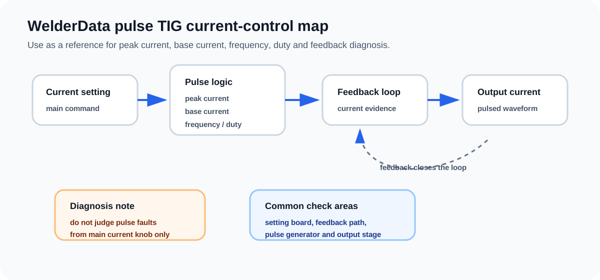
Peak, base, frequency and duty
The peak-current command sets the high-current portion of the pulse. The base-current command sets the lower sustaining current. Pulse frequency and duty ratio determine how often and how long the current remains at each level. If the welder produces normal steady TIG output but pulse mode behaves incorrectly, inspect the pulse command section before replacing the main power stage.
Useful evidence includes whether peak and base settings change the output, whether pulse frequency changes the rhythm, whether duty control affects time balance and whether current feedback follows the expected waveform.
Repair routing table
| Symptom | Most useful separation | Next check |
|---|---|---|
| Steady TIG works, pulse mode does not | Pulse generator / setting path | Check peak/base/frequency/duty command section and mode selector. |
| Pulse rhythm exists but current levels wrong | Current-command or feedback path | Check feedback sensor, current setting path and display/control board. |
| Pulse frequency fixed or unstable | Timing oscillator / digital setting path | Check frequency command, timing network or controller output. |
| No TIG output in any mode | Not a pulse-only fault | Return to auxiliary rails, torch switch, protection and main output diagnosis. |