Circuit
TIG Torch Switch, Gas Pre-Flow and Post-Flow Control Circuit
A WelderData control reference for separating TIG torch command, gas solenoid drive, output enable and gas-delay timing faults.
Database summary
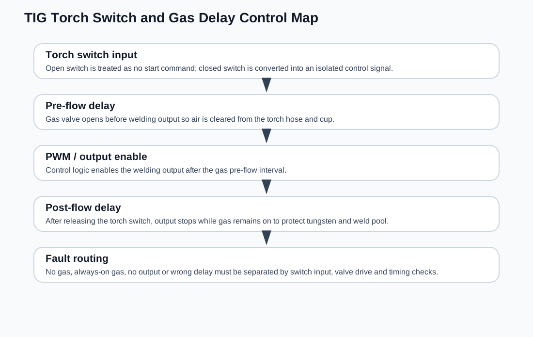
This WelderData record organizes TIG torch-switch, gas pre-flow, welding-output enable and post-flow timing into one service path. The key repair idea is that torch switch response, gas valve drive and welding output enable are related but not identical. A machine can have gas without output, output logic without gas, or a gas valve stuck on after the switch is released.
The reference timing pattern uses pre-flow to clear air from the torch before output begins and post-flow to protect the tungsten and weld pool after output stops.
WelderData control map
Torch switch input
Some TIG control boards isolate the torch switch before converting it into a start command. A measured low command state with the torch switch open and a higher command state with the switch closed can be normal, depending on the board design. The important point is not the exact connector voltage alone, but whether the control board recognizes switch closure and moves the gas/output sequence forward.
If pressing the torch switch produces no gas and no output response, diagnose switch wiring, connector pins and the isolation/input stage first. If gas works but output remains disabled, move downstream to the PWM enable, protection input and output-control path.
Gas pre-flow and post-flow behavior
| Function | Typical role | Repair interpretation |
|---|---|---|
| Pre-flow | Opens gas before output starts | Clears the torch hose and cup before arc start. |
| Output enable | Allows welding PWM / output after the start sequence | May be blocked by protection even if gas valve opens. |
| Post-flow | Keeps gas on after output stops | Protects tungsten and hot weld pool. |
| Gas valve drive | Solenoid transistor or relay path | Failure can cause no gas or always-on gas. |
Service timing ranges vary by board family, but practical TIG control often provides short pre-flow and a longer adjustable post-flow. If the torch switch works but timing is wrong, focus on the timing network, valve-driver transistor and control-board enable logic before condemning the gas valve.
Fault routing
- No gas: check torch switch input, gas solenoid supply, valve coil and driver transistor.
- Gas always on: check valve driver transistor, output latch state and post-flow timing path.
- Gas but no welding output: check output enable, protection input and PWM shutdown path.
- HF but no gas: separate HF-start relay control from the gas valve control circuit.
- Wrong delay: verify timing potentiometer, capacitor leakage and control-board ground reference.