Repair workflow
Welding Machine Field Test Instruments Checklist
A repair workflow for turning multimeter, clamp meter, insulation tester, oscilloscope, lamp limiter, dummy load, pressure gauge and thermal evidence into a usable welding-machine repair record.
Why this workflow exists
Many repair records say only "checked with a meter" or "powered on normally." That is not enough for a welding-machine database. The tool, range, test condition and stop condition matter. This page turns field instruments into structured evidence before a technician replaces a board, IGBT, SCR, contactor or transformer.
Evidence map
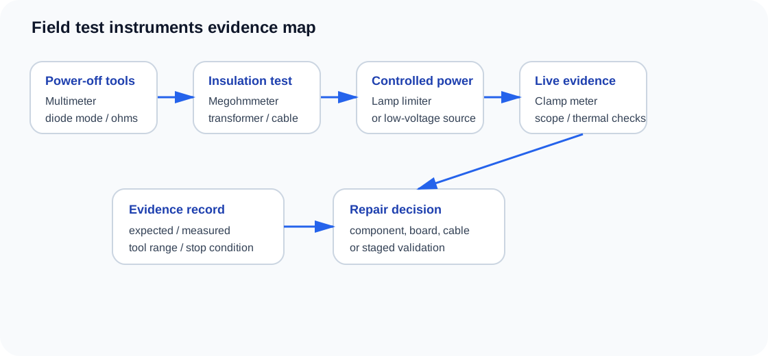
Instrument-to-evidence table
| Instrument | Best use in welder repair | Common mistake | Record field |
|---|---|---|---|
| Digital multimeter | Continuity, diode-mode checks, control rails, contactor coil resistance, potentiometer movement. | Using one resistance reading to declare a board good. | Range, polarity, expected value, measured value. |
| Clamp meter | Compare welding current, input current, feeder motor current or contactor load current. | Comparing panel current to arc current without knowing where the meter is reading. | Clamp location, current range, load condition. |
| Insulation resistance tester | Transformer, motor, cable, heater and winding-to-frame checks after moisture, burning or repeated fuse faults. | Using it on semiconductor boards or low-voltage electronics. | Test voltage, disconnected parts, insulation result. |
| Oscilloscope | PWM, gate-drive symmetry, SCR trigger, HF start command, current-feedback ripple. | Connecting the ground clip into a live primary without isolation planning. | Probe point, reference ground, waveform amplitude and timing. |
| Lamp limiter / current limiter | First restart after power-device failure, short evidence and staged power-up. | Using a dim lamp as proof that every driver branch is healthy. | Lamp behavior, disconnected loads, bus response. |
| Dummy load / resistor bank | Controlled output validation after repair before full welding load. | Testing at full power too early after a power-stage repair. | Load value, current, voltage, time and heat. |
| Thermometer / thermal camera | Hot joint, diode, SCR, transformer, reactor, contactor and cable checks. | Calling heat normal without duty-cycle context. | Ambient, load time, part temperature, duty condition. |
| Pressure / flow gauge | Plasma air pressure, MIG gas flow, TIG gas flow, water-cooled torch protection. | Replacing a control board before checking gas/air permission signals. | Pressure/flow value and switch state. |
Field test sequence
| Step | What to do | Do not continue if |
|---|---|---|
| 1. Identify symptom | Record no output, weak arc, no gas, no wire feed, high-frequency fault, protection light or repeated device failure. | The symptom is unclear or changes with cable movement. |
| 2. Power off evidence | Check shorts, diode paths, loose cables, contactor coils, torch switch and obvious burning. | DC bus capacitors are not discharged. |
| 3. Isolation evidence | Separate primary power path, control board, driver board, load cable or torch path when possible. | A board is still connected to a known shorted load. |
| 4. Controlled power | Use lamp limiter, lower voltage or staged power where appropriate. | Limiter stays bright, smoke appears, relay chatters or protection repeats. |
| 5. Live measurement | Measure rails, PWM, trigger, feedback, current or waveform only after the test condition is safe. | Probe reference or grounding is uncertain. |
| 6. Validation | Validate at low risk, then partial load, then normal welding condition. | Driver, feedback or thermal evidence is still missing. |
Related WelderData pages
Printable maintenance record
Use the interval checklist with the field-instrument list.