Repair methodology
Welding Machine Repair Methodology for Board-Level Diagnosis
A WelderData workflow reference for moving from a visible welding-machine symptom to safe measurements, board isolation, repair action and post-repair validation.
Database summary
This WelderData entry describes a practical diagnostic method for welding machine repair. It is not a single machine model page. It is the common repair workflow behind the model, fault, board, circuit, repair-case and tool pages in this database.
For inverter welders, TIG machines, MIG / CO2 machines, plasma cutters and submerged arc systems, the useful repair path is rarely “replace the visibly burned part and power on.” A safer path is: record the symptom, inspect without power, identify shorted sections, power the machine in a controlled way, confirm the control rails and protection signals, isolate the failed board section, repair the root cause, and validate with staged power-up.
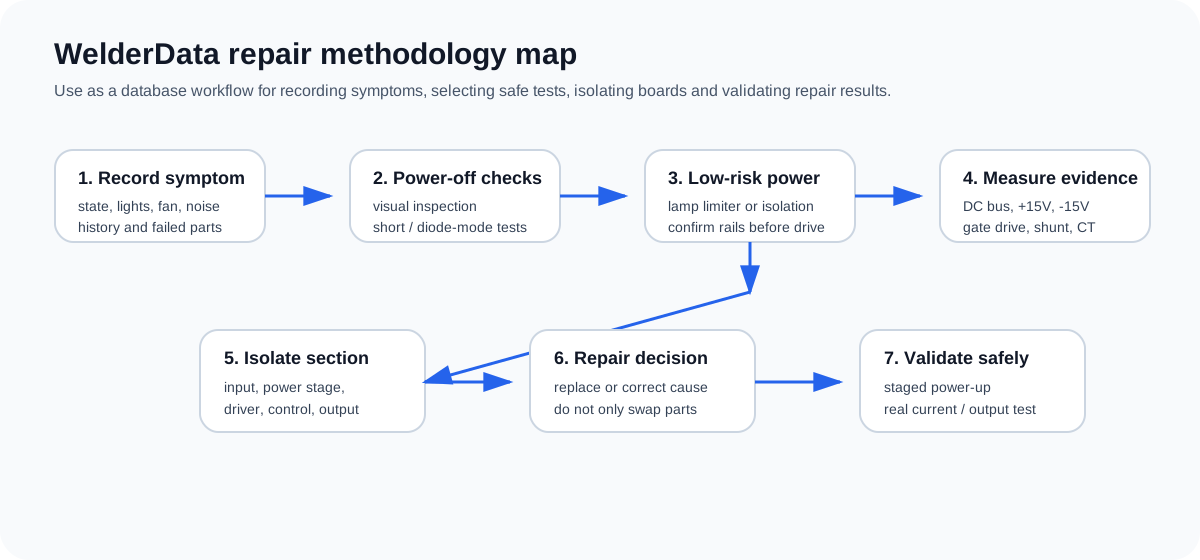
Technician requirements before diagnosis
A useful repair record starts before the multimeter touches the board. The technician should understand the welding process, the machine family and the control architecture. A ZX7 inverter, an MZ / ZD5 thyristor submerged arc source, a TIG HF-start machine and a CO2 / MIG wire-feeder system do not fail in the same way.
Process knowledge
Know whether the machine is SMAW, TIG, MIG / MAG, plasma or SAW. The output path, trigger logic, gas path and control feedback change with the process.
Electrical architecture
Identify the input stage, DC bus, inverter or SCR output stage, auxiliary supply, control board, driver board, feedback path and output rectifier.
Measurement discipline
Do not mix stable DC rail checks with pulse checks. +15V, +5V and DC bus readings are different from gate-drive pulses or SCR trigger pulses.
Repair records
Record observed symptom, test point, normal value, abnormal value, repair action and final validation so the case can become reusable diagnostic data.
Step 1: Record the symptom before opening the machine
The first diagnostic input is not a component value. It is the symptom pattern. A machine that has no display, a fan that runs with no output, a protection light, a lamp limiter that stays bright, a TIG torch with gas but no HF, or a MIG feeder with motor but no gas are different entry points.
| Record item | Why it matters | Example WelderData routing |
|---|---|---|
| Power-up state | Display, fan, relay and indicator lamps reveal whether auxiliary rails or control logic are alive. | No display → auxiliary supply path; fan runs but no output → control / driver / protection path. |
| Protection behavior | Fault light, undervoltage, overcurrent or overheat state may block PWM or output enable. | Protection light → feedback, CT, thermal switch, current-sense or control board shutdown. |
| Process symptom | TIG, MIG, plasma and SAW faults have process-specific paths. | TIG no HF, MIG no wire feed, plasma no pilot arc, SAW no wire retract. |
| Repair history | A replacement IGBT that failed again points toward driver, snubber, output rectifier or control problems. | Repeated IGBT failure → gate-drive precheck before installing new devices. |
Step 2: Power-off inspection and resistance checks
Before energizing the machine, WelderData treats power-off checks as the first safety filter. This includes visual inspection, smell, damaged insulation, loose terminals, cracked solder, burned resistors, cracked IGBTs, shorted bridge rectifiers, output diodes and DC bus capacitors that remain charged.
Power-off checks should focus on isolating dangerous short circuits. A bright lamp limiter, tripping breaker or blown fuse usually should not be debugged by repeated full-power starts. The safer method is to check input bridge, DC bus, IGBT / MOSFET modules, output fast-recovery diodes, snubber parts and auxiliary supply shorts before restoring normal mains power.
- Use ohms or diode mode only after the DC bus has been safely discharged.
- Compare symmetrical branches when the circuit has multiple identical driver outputs or power devices.
- Do not trust a single in-circuit reading if parallel paths are present; isolate connectors or modules when needed.
- Document whether the reading is measured in circuit, out of circuit, diode mode or resistance mode.
Step 3: Controlled power-up instead of direct full-power testing
When the short-circuit risk is unclear, use a controlled power-up method. In the WelderData database this often appears as a lamp-limiter check, isolated control-board test, separated high-voltage DC bus test, or staged power-up after IGBT repair.
| Controlled test | Useful when | Stop condition |
|---|---|---|
| Series lamp / lamp limiter | Input short, suspicious DC bus, unknown IGBT state. | Lamp stays bright, relay chatter, smoke, abnormal bus behavior. |
| Control board bench supply | Signal board or display logic needs verification before connecting power stage. | Wrong current draw, missing logic rails, abnormal heat. |
| Disconnected DC bus first start | After IGBT or driver repair when the control section must be verified first. | Protection active, missing panel response, no control rails. |
| External shunt / current meter test | Panel current display may be simulated or miscalibrated. | Real current does not match expected output behavior. |
Step 4: Separate rails, pulse signals and feedback signals
A common mistake is to treat every point on the board as a stable DC voltage. Welding machines use multiple signal types. Auxiliary power rails should be stable. Gate-drive transformer primaries may show pulse activity rather than a steady voltage. SCR trigger boards require synchronization and phase-shift pulses. Current feedback may be a millivolt shunt signal, CT signal or Hall sensor signal.
Step 5: Isolate by machine section
The practical repair task is to narrow the fault to a section, not to guess a component immediately. Most WelderData pages use a section-first approach.
| Section | Typical evidence | Next check |
|---|---|---|
| Input / rectifier / DC bus | Breaker trips, lamp limiter bright, no bus, wrong bus. | Input bridge, soft-start, relay, bus capacitor, boost path. |
| Auxiliary power | No display, fan dead, relay not active, missing 24V / 15V / 5V. | PWM supply IC, transformer, rectifier, regulator, optocoupler feedback. |
| Control board | Rails present but no PWM, shutdown active, wrong feedback. | Controller IC, reference voltage, protection input, current feedback. |
| Driver board | Repeated IGBT failure, uneven gate branches, weak turn-off. | Gate resistor, fast diode, driver transformer, UVLO, DESAT, bias supply. |
| Output rectifier / choke | No output, shorted output, unstable arc, fast diode failure. | Fast recovery diodes, output choke, snubber, output terminals. |
| Process control | MIG no wire feed, TIG no HF, plasma no arc, SAW no retract. | Torch trigger, gas valve, feeder motor, HF board, arc-voltage feedback. |
Step 6: Repair cause, not only the visible failed part
Visible damage is often the result, not the root cause. A shorted IGBT may have been caused by weak gate drive, missing negative bias, damaged snubber capacitor, shorted output diode, overcurrent feedback failure, heatsink pressure problem or incorrect staged power-up. A burned relay contact may be caused by current switching at the wrong time. A TIG gas valve stuck open may be a transistor or timing-control issue, not only the valve.
WelderData repair entries should therefore record both the failed part and the reason the part is likely to have failed. This is the difference between a parts list and a repair database.
Step 7: Validate with staged power-up and real output evidence
A repair is not complete when the machine powers on. Validation should confirm that the control board, power stage and real output agree. For an inverter welder this may mean DC bus confirmation, no-load output, lamp-limiter clearance, driver pulse presence and real current measurement. For TIG it may mean gas pre-flow, HF cut-off, arc transfer and post-flow. For MIG it may mean torch trigger, gas, wire feed, voltage control and crater-fill behavior.
How WelderData turns repairs into reusable database entries
Each good repair note should become structured information. The preferred structure is:
- Symptom: what the user or technician observes.
- Machine family: ZX7, TIG, MIG, plasma, MZ / ZD5, or another platform.
- Safety state: discharged bus, lamp limiter, disconnected high-voltage stage or bench supply.
- Measurement evidence: test point, normal value, abnormal value and instrument mode.
- Likely section: input, auxiliary, control, driver, output or process section.
- Repair action: part replacement, solder repair, connector correction or calibration.
- Validation: staged power-up, DC bus, no-load output, real current, gas / wire / HF / arc behavior.
Related WelderData tools and workflows
Field evidence and maintenance extensions
Use these supporting workflows when the repair record needs stronger measurement discipline or when a fault may be caused by service condition rather than board failure.
Symptom index and architecture routing
Use these routing pages when the first question is not a board name but a visible symptom or machine architecture.
Separate display command, PWM decision, gate evidence and real arc current
Many inverter welder mistakes start when the technician treats a lit display, a moving current knob or an open-circuit voltage reading as proof of welding output. A repair record should separate the command layer from the real arc layer.
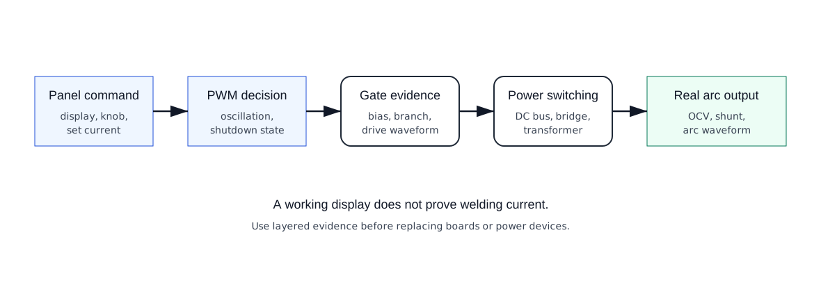
| Layer | Evidence to record | Common wrong conclusion |
|---|---|---|
| Panel command | Potentiometer/set voltage, display response, mode switch, torch trigger state. | “The display works, so the control board is good.” |
| PWM decision | Oscillator, shutdown pin, protection latch, current-limit input, reference voltage. | “No gate pulse means the PWM IC is bad.” |
| Gate evidence | Positive/negative bias, branch symmetry, transformer output, gate resistor and clamp path. | “All gates are fine because one branch has a pulse.” |
| Power switching | DC bus, bridge device, snubber, transformer primary, output rectifier. | “Open-circuit voltage means the power stage is healthy.” |
| Real arc output | Shunt/CT current, arc voltage, load test, waveform under controlled condition. | “The panel current is the welding current.” |
PWM, feedback and protection evidence before board replacement
For no-output and current-not-adjustable faults, separate the command signal, oscillator, PWM output, shutdown/protection state and gate-drive transfer before replacing the main board or IGBT module. A fan or display only proves auxiliary power; it does not prove PWM permission.
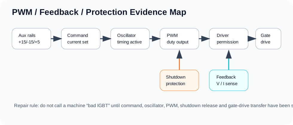
Use this chain in repair records: VCC present → reference present → oscillator present → shutdown released → PWM output present → driver stage receives pulse → gate branches are symmetric → real current is confirmed under staged power-up.
Separate display command, PWM decision, gate evidence and real arc current
Many inverter welder mistakes start when the technician treats a lit display, a moving current knob or an open-circuit voltage reading as proof of welding output. A repair record should separate the command layer from the real arc layer.
| Layer | Evidence to record | Common wrong conclusion |
|---|---|---|
| Panel command | Potentiometer/set voltage, display response, mode switch, torch trigger state. | “The display works, so the control board is good.” |
| PWM decision | Oscillator, shutdown pin, protection latch, current-limit input, reference voltage. | “No gate pulse means the PWM IC is bad.” |
| Gate evidence | Positive/negative bias, branch symmetry, transformer output, gate resistor and clamp path. | “All gates are fine because one branch has a pulse.” |
| Power switching | DC bus, bridge device, snubber, transformer primary, output rectifier. | “Open-circuit voltage means the power stage is healthy.” |
| Real arc output | Shunt/CT current, arc voltage, load test, waveform under controlled condition. | “The panel current is the welding current.” |
PWM, feedback and protection evidence before board replacement
For no-output and current-not-adjustable faults, separate the command signal, oscillator, PWM output, shutdown/protection state and gate-drive transfer before replacing the main board or IGBT module. A fan or display only proves auxiliary power; it does not prove PWM permission.
Use this chain in repair records: VCC present → reference present → oscillator present → shutdown released → PWM output present → driver stage receives pulse → gate branches are symmetric → real current is confirmed under staged power-up.
Related repair map
Follow the evidence path from symptom to measurement, circuit and repair case.