Model family
Panasonic RF2 / YC-300/500 Inverter CO2 Welders Repair Reference
Board-level reference for RF2-style inverter CO2 welders where E-code logic, IGBT gate-drive waveforms, CT feedback, wire feeder and gas valve evidence must be separated before parts replacement.
Database summary
This WelderData record covers the Panasonic RF2 / YC-300RF2HGE and YC-500RF2HGE style inverter CO2 welding platform as a repair-reference family. It is useful because the machine combines an inverter power section, CPU PCB, I/F PCB, driver PCB, CT current feedback, wire feeder, gas valve, torch command and error-code logic.
For this platform, a fault should not be routed only by the final welding symptom. The E-code, board test point, feedback voltage, gate-drive evidence and feeder/gas sequence must be read together before replacing expensive IGBT modules or control boards.
System areas to separate
| Area | Evidence to collect | Repair interpretation |
|---|---|---|
| Power input and inverter | Input phase, over/undervoltage E-code, contactor and main rectifier evidence. | Do not blame the feeder if the power source never reaches output-ready state. |
| CPU PCB / I/F PCB | +15V / -15V rails, TP signals, VP reference, E-code latch and connector condition. | Many RF2 faults are board-interface faults rather than failed power semiconductors. |
| Driver PCB and IGBT gate | Safe waveform check, +14V / -14V gate bias, pulse timing and TS ON/OFF meter behavior. | Gate-drive evidence is required before a replacement IGBT is trusted. |
| CT current feedback | TP7(Iao), zero-current offset and current-to-voltage ratio. | False current feedback can trigger E2 or unstable arc diagnosis. |
| Wire feeder and gas circuit | Torch switch, feeder connector, gas valve, TP6(VG), slow feed and burn-back settings. | Gas or feeder symptoms often belong to the control interface, not the main inverter. |
Main power circuit structure
The RF2 platform should be read as an inverter CO2 welding power source, not only as a wire-feeder fault machine. The main path includes a three-phase input section, main contactor, rectifier, DC-link capacitor bank, IGBT inverter unit, inverter transformer, primary-side diode path, secondary rectifier diodes, DC reactor, current-detection shunt or CT feedback and output terminals.
| Power-stage area | Service evidence | Why it matters |
|---|---|---|
| Input rectifier / contactor | Input phase, contactor pull-in and E4/E5 voltage alarms. | Input faults can mimic board or feeder faults. |
| DC bus and capacitor bank | Bus charge behavior, discharge safety and abnormal short evidence. | Do not energize the inverter if the bus or capacitor bank is suspect. |
| IGBT inverter and transformer | Offline IGBT test, gate-drive waveform and safe isolation check. | Replacement modules can fail immediately if drive evidence is not verified. |
| Secondary rectifier / DC reactor | Output diode short, reactor/output path and E2/E7 behavior. | Secondary shorts can be routed as output abnormal or overcurrent faults. |
| Current feedback | TP7(Iao), shunt/meter comparison and zero-current offset. | False current feedback can distort current regulation and E-code routing. |
RF2 repair map
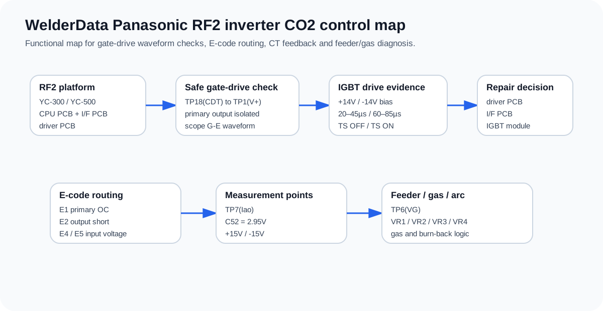
WelderData functional map for RF2 gate-drive checks, E-code routing, CT feedback and wire-feed/gas diagnosis.