Model family reference
ZX7-III Stick/TIG Inverter Welder Repair Reference
A redrawn, English-only reference for ZX7-III power conversion, output behavior and practical diagnostic checkpoints.
What this model page is for
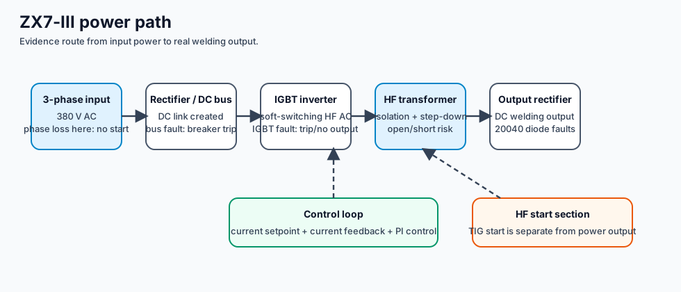
ZX7-III stick/TIG inverters are useful because they connect a common symptom set — no output, breaker trip, no OCV, TIG no start, remote not working and protection light — to one clean power-path model.
Field checkpoints
| Area | Normal evidence | Fault clue |
|---|---|---|
| Input / rectifier | Three-phase input is present and rectified into a DC bus. | Phase loss, input protection or bridge failure can stop startup or trip the breaker. |
| IGBT inverter | Gate drive is permitted and the inverter switches. | Shorted IGBT, lost soft-switching condition, bad snubber or driver damage can cause trip/no output. |
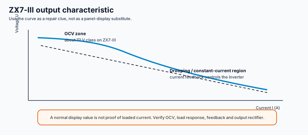
| Output rectifier | OCV and loaded current appear at the welding output. | 20040/output diode failure can produce no OCV, weak output or unstable current. |
| Control / feedback | Current setpoint, current feedback and PI loop agree. | Current cannot adjust, random display values or feedback offset indicate control-loop evidence is needed. |