Chip
SG3525 PWM Controller Reference for Inverter Welder Control Boards
SG3525 / SG3525A PWM controller repair reference for inverter welder control boards: 5.1V reference, oscillator, soft-start, shutdown and A/B push-pull output evidence.
Database summary
SG3525 / SG3525A is a voltage-mode PWM controller used on many inverter welder control boards, especially older ZX7-style, MOSFET bridge and push-pull driver-transformer designs. In a repair workflow, it should not be treated as a black-box “PWM chip.” A no-output board can have SG3525 supply present and still be held off by soft-start, shutdown, error-amplifier, protection, VRD or driver-stage faults.
Welder control-board evidence map
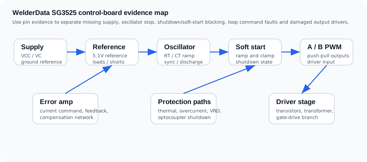
Repair pin evidence table
| Evidence area | What to confirm | Repair interpretation |
|---|---|---|
| VCC / VC supply | The IC supply and output-driver supply are present with a correct ground reference. | Low supply can mimic a bad SG3525. Check auxiliary supply, connector, zener, startup resistor and local decoupling before replacing the IC. |
| 5.1V reference | The internal reference is stable and not pulled down by external loads. | A missing reference can be an IC fault, but it can also be caused by a shorted external circuit connected to the reference rail. |
| RT / CT oscillator | The timing capacitor node shows oscillator activity and the discharge path is not shorted or open. | No oscillator means no PWM. Check timing resistor, timing capacitor, sync/discharge components and solder cracks before assuming the IC is dead. |
| Soft-start pin | The soft-start voltage rises normally after power-on. | If the pin is clamped low, the board may stay in startup forever. Check soft-start capacitor, diode clamp and shutdown-related transistor. |
| Shutdown pin | Shutdown is inactive during normal run command. | Active shutdown points to thermal, overcurrent, VRD, optocoupler, panel command or protection feedback path. |
| Error amplifier inputs | Current command and feedback are reasonable; compensation node is not railed. | An abnormal feedback amplifier can force minimum duty or maximum duty. Separate command/feedback evidence before changing SG3525. |
| A / B outputs | Complementary push-pull PWM appears with similar amplitude and duty. | One missing side can be IC damage, output loading, downstream transistor short or transformer primary fault. |
| Driver stage input | PWM reaches the small transistor / driver-transformer stage. | If SG3525 outputs are good but gate drive is missing, move to driver transistors, transformer primary, gate resistors and branch loads. |
No-PWM troubleshooting order
- Confirm auxiliary rails before probing PWM pins.
- Confirm SG3525 VCC / VC and the 5.1V reference.
- Check whether shutdown or soft-start is holding the IC off.
- Check RT / CT oscillator evidence.
- Check the error-amplifier command and feedback inputs.
- Check A / B output symmetry with the power stage isolated when required.
- Only then decide whether SG3525 itself, the external loop, or the driver stage is the fault.
Common SG3525 welder symptoms
| Symptom | Likely evidence path | Do not conclude too early |
|---|---|---|
| Fan/display works but no welding output | Aux rail → SG3525 supply → shutdown/soft-start → outputs → driver stage | Do not replace IGBTs before confirming PWM and shutdown evidence. |
| Reference voltage missing | VCC, IC loading, external reference load, damaged IC | A shorted external op-amp or comparator load can pull the reference down. |
| Oscillator absent | RT/CT components, discharge pin, sync path, IC supply | The timing network is a common field fault and is easier to verify than replacing the chip. |
| Only one PWM output active | Output loading, downstream transistor, transformer primary, IC output damage | Disconnecting a suspect load may be needed for bench isolation. |
| PWM appears but IGBT has no drive | Driver transistor pair, driver transformer, gate resistors, branch symmetry | This is a driver-board fault, not necessarily an SG3525 fault. |