Circuit reference
MOSFET Inverter Stick Welder Power Stage
MOSFET inverter stick welders are common in compact portable arc welders. Repair should not stop at the visibly blown MOSFET: the DC bus, gate-drive path, snubber parts, transformer primary and secondary rectifier must be separated before a safe restart.
Database summary
A MOSFET inverter stick welder power stage typically uses a mains rectifier and DC bus to feed a high-frequency switching section. The switches drive a high-frequency transformer, and the secondary side uses fast rectifier diodes and an output inductor to supply welding current.
When a MOSFET fails short, the visible part is only the end of the fault chain. The surrounding driver, gate resistor, clamp diode, snubber capacitor, bus capacitor, transformer primary and output rectifier can all participate in the failure.
WelderData fault-routing map
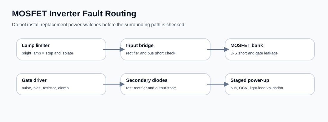
Power-off checks before replacing MOSFETs
| Check | What to measure | Interpretation |
|---|---|---|
| Input rectifier | Diode mode across AC-to-DC bridge terminals | A shorted bridge can keep the lamp limiter bright even with inverter switches removed. |
| DC bus capacitor | Resistance rise / discharge behavior and visible swelling | A hard short or no charge behavior must be resolved before switch installation. |
| MOSFET bank | Drain-source short and gate-source leakage | One shorted device can mask driver or transformer-side problems. |
| Gate resistor / clamp | Compare all parallel branches | A damaged gate path may destroy new MOSFETs immediately. |
| Secondary rectifier | Diode-mode test of fast recovery diodes | A shorted secondary diode can overload the inverter at restart. |
Controlled restart principle
After the shorted section is repaired, restart should be staged. A lamp limiter or controlled input should confirm that the DC bus is not still shorted. The driver should show proper bias or pulse evidence before the power switches are trusted. Open-circuit output voltage should be measured before a live welding load test.
If the lamp remains bright, if gate drive is asymmetric, or if the secondary rectifier reads short, stop the restart sequence and return to section isolation.