Circuit
Digital Arc Power Source Feedback Control
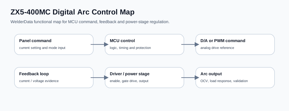
Digitally controlled welding power sources combine panel input, logic control, analog scaling, feedback measurement and driver enable. Repair diagnosis must prove which layer is missing before replacing a board.
Database summary
A digital arc power source does not remove analog repair work. It adds a logic layer above the familiar current feedback, voltage feedback, driver and output circuits. The repair question becomes: is the output wrong because the command is wrong, the feedback is wrong, the protection state is active, the driver is disabled, or the power stage cannot respond?
Control-loop layers
| Layer | What to verify | Typical evidence |
|---|---|---|
| Control supply | Logic rail, reset, panel power and stable reference. | Dead display, MCU not running, random key response. |
| Command input | Panel setting, mode selection, local/remote path and harness. | Command does not change, wrong mode, remote input overrides panel. |
| Command output | D/A, filtered PWM, analog reference or enable signal from logic section. | Panel changes but regulator reference does not move. |
| Feedback input | Current shunt, Hall sensor, voltage divider and scaling circuit. | Output exists but display/feedback disagrees with external meter. |
| Protection state | Thermal, overcurrent, undervoltage, overvoltage and fault latch. | Machine enables briefly then disables or refuses driver output. |
| Driver / output | Gate drive, SCR trigger, inverter bridge, rectifier or output reactor. | Command and feedback look valid but output cannot follow. |
WelderData control map
Repair caution
Do not condemn the MCU board just because the welding output is absent. A digitally controlled machine can be held off by protection inputs, missing feedback, local/remote selection, panel command failure or driver-stage faults. Conversely, a healthy power stage cannot regulate correctly when the feedback scaling or command reference is wrong.