Circuit
ZX7 Series Control Board Calibration: Current Display, Feedback Zero and Shunt Reference
A WelderData circuit reference for separating preset display behavior, feedback amplifier zero, shunt signal calibration and real output-current verification.
Database summary
This WelderData record organizes ZX7 series control-board calibration checks that appear after current-display, feedback or output-current repairs. The calibration sequence is not a substitute for a safe load test. It is a way to keep current preset, feedback zero, shunt signal and panel display evidence separate.
The key repair principle is that a current number on the panel is not automatically the same thing as real welding current. The control board can display a preset value, respond to potentiometer movement and still require feedback-zero or shunt-reference work before the final output-current result is trusted.
WelderData calibration map
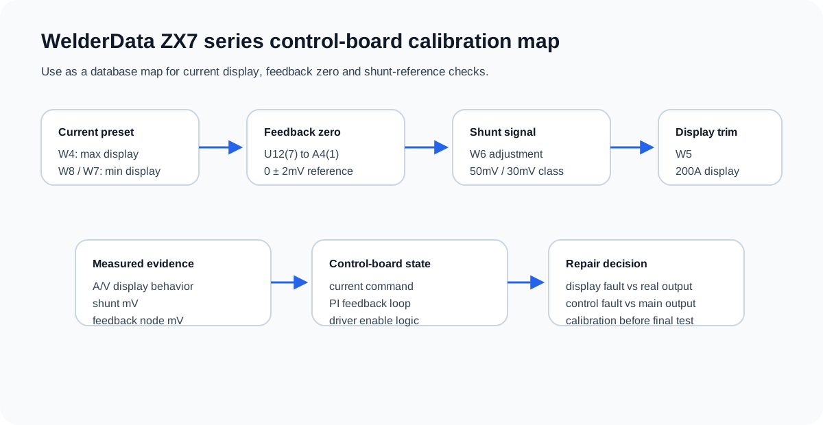
Current preset display checks
For ZX7 series control boards, the current-set potentiometer and display path should be checked before deeper feedback repair. In the documented calibration pattern, the current command is moved to maximum and W4 is used to align the maximum display value for the machine class, such as 315A, 400A or 500A. The command is then moved to minimum and W8, or W7 on some red-case control boards, is used to align a 20A minimum display reference.
This stage checks display scaling and command behavior. It does not prove that the machine is producing that current at the output terminals.
Feedback amplifier zero
The feedback-zero step is used to prevent the control board from treating a false feedback offset as real welding current. The reference used in this ZX7 series note is U12 pin 7 relative to A4 pin 1, adjusted to 0 ± 2mV with W7. Some red-case board variants use W8 and a different connector reference such as A5 pin 6.
If feedback zero is wrong, the machine may display an abnormal preset, respond poorly to current adjustment or regulate as though output current is already present. This is why feedback zero belongs before final output-current judgment.
Shunt reference and display alignment
| Adjustment point | Service purpose | WelderData interpretation |
|---|---|---|
| W4 | Maximum current display alignment | Use after confirming current command path and display response. |
| W8 / W7 | Minimum current display alignment | Typically aligned around a 20A reference depending on board variant. |
| W7 or W8 variant | Feedback amplifier zero | U12 feedback node should be near zero mV against the specified board reference. |
| W6 | Shunt signal calibration | Used with output short/load condition and machine-class mV reference. |
| W5 | 200A display alignment | Aligns display after shunt feedback has been set. |
The document pattern includes a 50mV class signal for 315A/400A units and a 30mV class signal for 500A units during the W6 adjustment. Some board-version notes mention 52mV for 315/400 and 31.5mV for 500. Treat these as board-family service references, not universal values for every ZX7 clone.
Calibration cautions
- Do not adjust the board before confirming the current potentiometer, remote/local switch and wiring.
- Do not rely only on the front-panel display when real output current is in question.
- Record the board version, model class and shunt mV reference used.
- Use an external current meter or shunt when confirming final output current.
- If TIG, remote or arc-force functions are abnormal, fix the functional fault before final current calibration.
TP + VR calibration table for ZX7-315 / 400 / 500 / 630
The dedicated PCB test-point workflow gives a rating-specific TP1-TP16 reference. For calibration, the most important service path is simple: confirm supply rails, confirm the current-class jumper, then use TP15, TP16 and TP4 with the correct VR controls.
| Calibration target | Measure | Adjust | Why it matters |
|---|---|---|---|
| Minimum current | TP15, about -0.4V reference | 1VR5 | Prevents low-current range and start-current complaints from being misread as IGBT faults. |
| Maximum current | TP16: 315=-6.3V, 400=-8V, 500=-10V, 630=-12.6V | 1VR4 | Matches command range to the machine current class. |
| Maximum clamp current | TP4: 315/400=4.05V, 500=5V, 630=6.3V | 1VR3 | Sets current limiting behavior; do not adjust until protection faults are resolved. |
Before any of these adjustments, verify TP12 +15V, TP13 -15V and TP14 +5V. Missing supply rails make calibration meaningless.