Repair workflow
Digital Arc Power Source Fault Routing
Use this workflow when a digitally controlled welding power source has display activity, command changes, protection behavior or output mismatch that cannot be diagnosed as a simple power-device failure.
Database summary
Microcomputer-controlled welding power sources need a different first pass than simple analog machines. The correct question is not only “is the power stage switching?” but “did the machine receive a valid command, allow output, read feedback correctly and enable the driver?” This workflow keeps those layers separate.
Fault-routing map
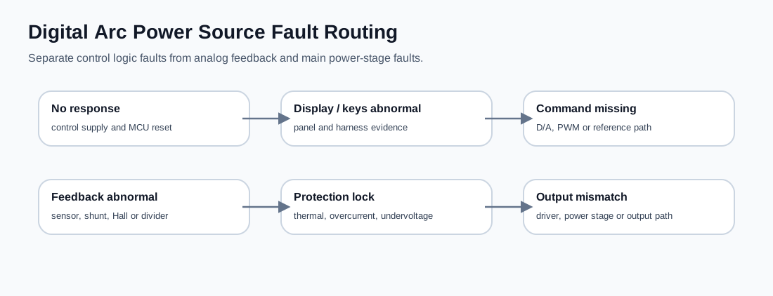
Routing table
| Symptom | First section to separate | Next check |
|---|---|---|
| Display dead or unstable | Control supply / reset | Check low-voltage rails, reset path, panel harness and main control supply. |
| Panel changes but output does not | Command output path | Look for analog reference, filtered PWM, D/A output or enable signal leaving the logic section. |
| Output exists but reading is wrong | Feedback or display scaling | Compare real output with external meter or shunt before calibration. |
| Output starts then stops | Protection latch | Check thermal, overcurrent, undervoltage, feedback abnormality and fault-clear conditions. |
| Command and feedback valid, no arc | Driver / main power stage | Move to driver pulse, gate bias, SCR trigger, inverter bridge and output rectifier checks. |
Minimum evidence record
- Machine family and control mode.
- Panel power and display state.
- Measured control rails.
- Command change evidence.
- Feedback sensor evidence.
- Protection or fault indication.
- Driver-enable state.
- External output measurement.