Circuit sequence
KLG-60 Plasma Cutter Gas, HF and Torch Sequence
A practical sequence page showing how compressed air, contactor enable, high-frequency start, torch consumables and transferred cutting arc interact in a KLG-60 air plasma cutter.
Why the KLG-60 sequence matters
Air plasma cutters can be misleading because several systems must work at the same time. The machine may have control power but no contactor action. It may have contactor action but no HF start. It may have HF start but no transferred cutting arc. It may cut thin material but fail on thicker plate because compressed air, consumable geometry or main current delivery is marginal. This circuit page turns the KLG-60 operating sequence into a practical inspection map.
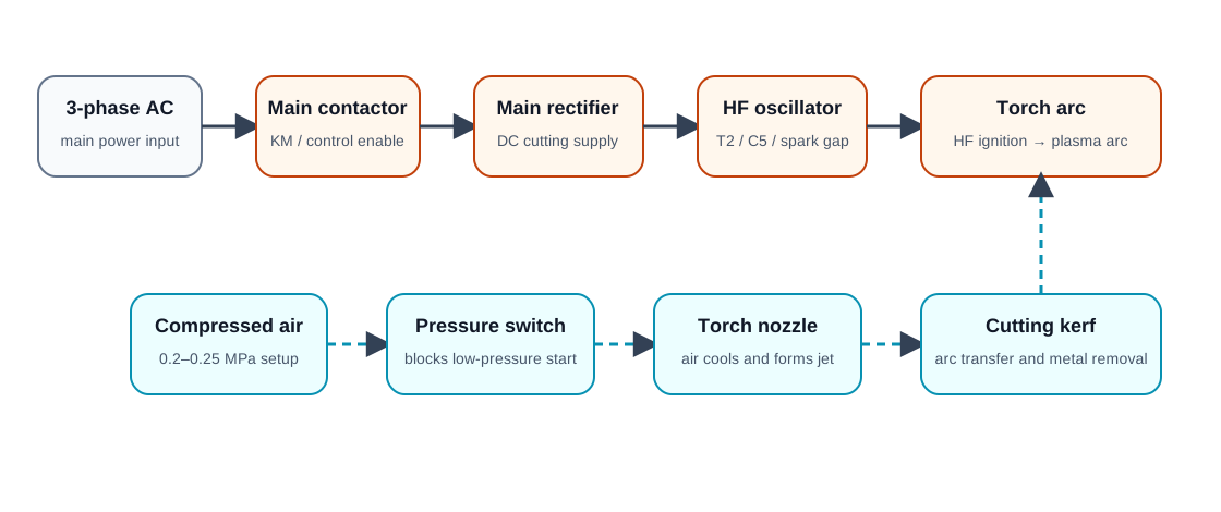
Electrical enable path
The electrical side begins with three-phase input and a main control path that energizes the main contactor. The WelderData circuit record identifies the input contactor, control transformer, rectifier/filter path, high-frequency oscillator and torch/control switches as related parts of the operating sequence. For repair work, the important point is not the exact physical layout of one production version; it is the order of permission.
- Confirm the incoming supply and input switch state.
- Confirm the control transformer secondary voltage and low-voltage control fuse path.
- Check the panel and torch switch chain.
- Check thermal relay and pressure-switch permission.
- Confirm contactor coil voltage before replacing the contactor.
- After contactor action is normal, proceed to main rectifier and HF start checks.
Gas-pressure path
The gas path is not secondary. It is a core part of arc formation. The WelderData KLG-60 record describes compressed air adjusted around 0.2–0.25 MPa for the cutting process, with pressure control participating in machine protection. If the pressure is too low, the pressure controller may stop the circuit or the arc may become weak. If the air is dirty, wet or restricted, the nozzle and electrode can burn quickly. If the pressure is excessive, arc stability and cut quality can also suffer.
| Check | What to verify | Repair implication |
|---|---|---|
| Regulator setting | Panel gauge adjusted to the expected operating range. | Wrong setting can block operation or destabilize the arc. |
| Pressure switch | Closes only when sufficient air pressure is present. | A bad switch can mimic electrical failure. |
| Air-water separator | Clean, drained and not restricting flow. | Water and dirt accelerate electrode/nozzle wear. |
| Hose and torch passage | No blockage, leak or severe restriction. | Weak air stream causes burnback and poor kerf quality. |
HF ignition path
The high-frequency start circuit forms the initial ionization path. A fault in the HF transformer, high-voltage capacitor, discharge gap, contactor contacts or wiring can leave the machine with normal fan and control response but no arc at the torch. If HF is present but the transferred arc is poor, check torch-to-work distance, work clamp continuity and consumable condition before replacing the HF section.
WelderData notes point to a practical spark-gap adjustment around 2–3 mm. This is a useful field reference, but it should not be treated as a universal value across all cutters. Always inspect the actual electrode shape, insulation distance, carbon tracking and manufacturer-specific construction before adjustment.
Torch and transferred arc path
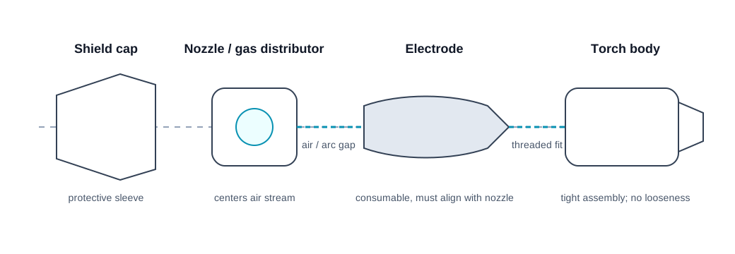
The torch changes electrical energy and compressed air into a cutting jet. A small mechanical problem can therefore look like a major electrical fault. If the electrode is not centered in the nozzle, the arc can strike the nozzle wall. If the shield cap or nozzle is loose, the air stream becomes uneven. If the workpiece clamp is poor, the pilot/HF action may occur but the transferred cutting arc remains weak.
For this reason, the torch should be inspected before board-level troubleshooting. Replace worn consumables, clean the gas distributor, tighten the torch body and verify the work clamp. Then retest the HF start and cutting transfer sequence.