Fault diagnosis
KLG-60 Plasma Cutter Fault Diagnosis
A symptom-first diagnostic guide for KLG-60 air plasma cutters: main contactor not pulling in, no high-frequency spark, weak cutting arc, automatic arc interruption, burned nozzle or electrode and poor kerf quality.
Symptom-first diagnosis
The WelderData KLG-60 fault table is valuable because it does not treat plasma-cutter repair as a single “no arc” problem. It separates contactor failure, gas-pressure and airflow problems, high-frequency start failure, torch-to-workpiece transfer problems, unstable arc behavior, consumable burning and poor cutting geometry. That is the correct way to diagnose plasma cutters in the field.
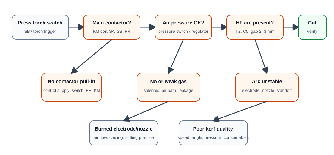
KLG-60 common faults and repair actions
| Symptom | Likely fault area | Repair direction |
|---|---|---|
| Main contactor does not pull in | Missing phase input, open control path, thermal relay action, low air pressure, failed switch or contactor coil. | Restore the three-phase input, reset or replace thermal/protection parts, raise air pressure to the required range and verify torch/control switches before replacing the contactor. |
| Air pressure and electrical supply appear normal, but pressing the torch switch gives no cutting arc | Control transformer, fuse, trigger path or missing output from the control circuit. | Check the air switch/pressure input, control transformer secondary, fuse path, panel switch and control relay chain. |
| Fan and indicators are normal, but no high-frequency spark appears | HF transformer, high-voltage capacitor, spark-gap distance, HF contactor or wiring fault. | Check HF transformer output, capacitor condition, spark gap and associated contactor contacts. Reset the spark gap to a practical 2–3 mm range. |
| HF spark exists, but the arc does not transfer well to the workpiece | Torch lead open, poor work clamp contact, nozzle-to-work distance too large, damaged torch insulation or weak cutting current. | Check work lead continuity, clamp contact, torch cable, nozzle distance and the main cutting-current path. |
| Nozzle touches the workpiece and arcs, but cutting does not penetrate | Main rectifier/current path weak, air pressure too high or too low, torch consumables damaged, or incorrect operating distance. | Inspect the rectifier and current path, adjust air pressure, replace damaged consumables and retest with correct torch standoff. |
| Arc stops automatically during cutting | Air pressure drops, pressure switch opens, cutting speed too slow, plate contact changes or protection circuit activates. | Stabilize compressed-air supply, verify pressure switch, clean torch path and keep cutting speed consistent. |
| Nozzle burns easily | Insufficient air flow, poor cooling, nozzle contact with workpiece, low air pressure, worn electrode or improper cutting technique. | Improve air volume and cleanliness, replace consumables, prevent nozzle contact and maintain correct standoff. |
| Electrode burns easily | Electrode and nozzle center misalignment, compressed air too low, cooling path blocked or torch assembly loose. | Install electrode and nozzle concentrically, tighten the torch, clean the air path and verify airflow before cutting. |
| Cutting arc becomes weak or air flow becomes very small | Closed panel air valve, blocked line, gas/water separator issue, compressor or external air-supply fault. | Open the valve, drain and clean the air-water separator, inspect the hose and restore compressor capacity. |
| Cut is slanted, bevelled or uneven | Electrode/nozzle wear, wrong torch angle, wrong standoff, excessive cutting speed variation or unstable air stream. | Replace consumables, hold torch perpendicular, keep distance steady and verify air pressure stability. |
| Cannot cut through the rated thickness range | Cutting speed too fast, air pressure abnormal, work cable/contact fault, weak main current or damaged torch parts. | Reduce speed, check work clamp, adjust air pressure, inspect torch and verify the main current path. |
Contactor does not pull in
A main contactor that does not pull in should not immediately be treated as a defective contactor. In the KLG-60 control concept, several conditions must be satisfied before the contactor can close. The input phases must be present, the panel and torch switch chain must be intact, the thermal relay must not be tripped, the pressure switch must see sufficient compressed air and the contactor coil itself must be able to energize.
The fastest field workflow is to divide the problem into three sections: input, permission and coil. Input means the machine has the correct supply. Permission means the low-voltage control chain allows operation. Coil means the contactor coil and its terminals receive the correct voltage. Only after those three checks should the contactor be replaced.
No HF arc or weak start
When the fan works and the control lights appear normal, but no high-frequency spark is produced, focus on the HF oscillator path. WelderData records identify a high-frequency transformer and capacitor/spark-gap circuit as part of the starting system. The spark gap is especially important. A gap that is too wide may not break down reliably; a gap that is too narrow may produce a weak or abnormal discharge. A practical service target is around 2–3 mm, with final adjustment depending on the hardware and insulation condition.
Do not test the HF circuit casually. High-frequency high-voltage energy can jump gaps and damage meters or insulation. Use insulated tools, keep probes away from the torch output path and avoid touching the work clamp while the machine is energized.
Consumable burning and poor kerf quality
Rapid nozzle or electrode burn is often blamed on the power circuit, but the KLG-60 failure table points strongly toward gas and torch conditions. A low air supply, contaminated compressed air, poor cooling, loose torch parts, excessive nozzle contact or off-center electrode alignment can damage consumables even when the main power section is normal.
Poor cut geometry should be judged after the consumables and air path are confirmed. A slanted or uneven kerf can come from worn electrode/nozzle parts, an angled torch, unstable cutting speed, wrong standoff or a weak transferred arc. Repair the mechanical and air-side problems first; then check the rectifier and main current path if the arc remains weak.