Plasma cornerstone fault
Plasma Cutter No Pilot Arc: Air, HF, Pilot DC and Transfer Diagnosis
A branch-by-branch repair workflow that prevents technicians from replacing the HF board before proving gas, pilot current and transfer evidence.
Symptom-first plasma workflow
First decide which start ingredient is missing
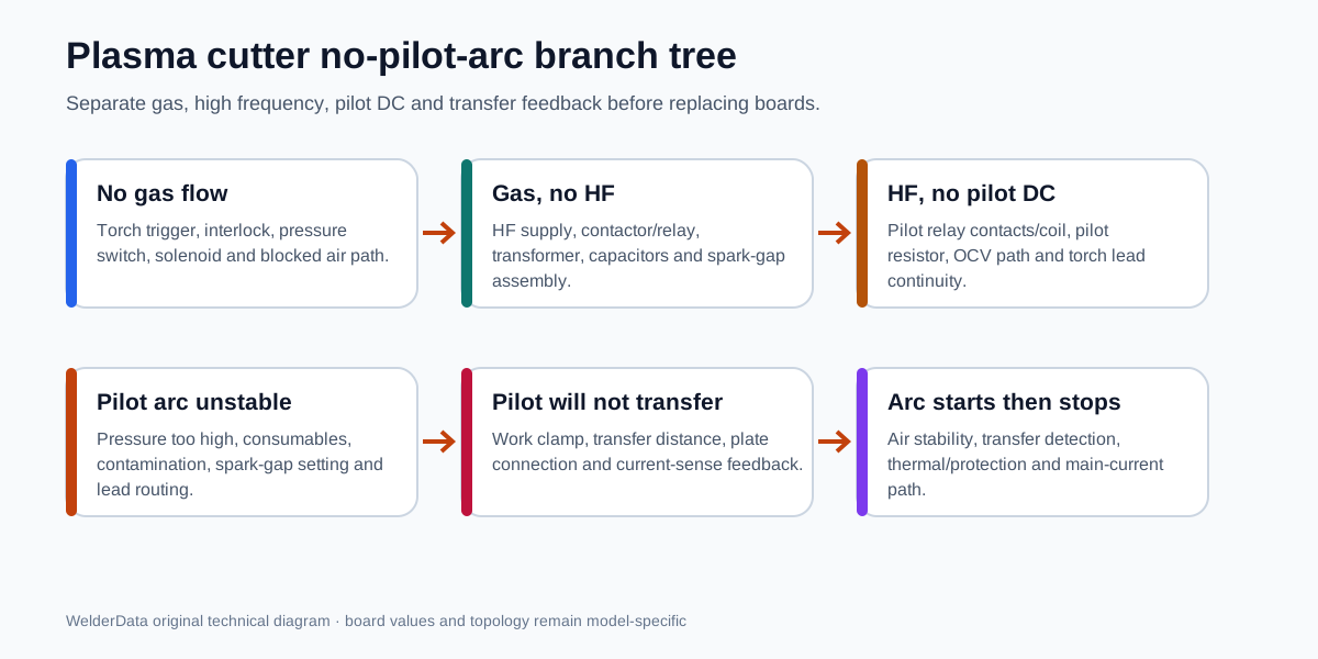
A typical high-frequency plasma start needs three ingredients at the torch: gas flow, DC open-circuit/pilot power and high-frequency ionization. After the pilot arc forms, the machine must detect transfer to the workpiece and change state. “No pilot arc” can therefore mean six different conditions: no gas, no HF, HF with no pilot DC, unstable pilot, pilot that will not transfer, or an arc that starts and immediately stops.
Normal start sequence
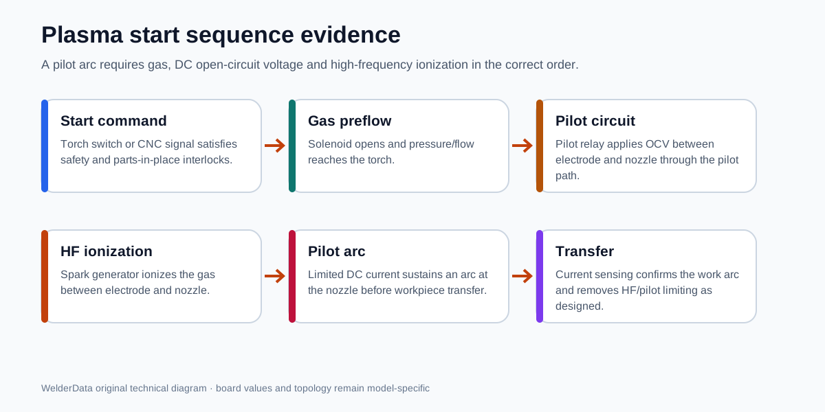
- The torch/CNC start command satisfies safety and parts-in-place interlocks.
- The gas solenoid opens and pressure/flow reaches the torch.
- The pilot circuit applies open-circuit voltage between electrode and nozzle through the designed relay/resistor path.
- The HF generator produces ionizing energy through the transformer, capacitors, spark gap and torch lead.
- Ionized gas supports limited pilot current between electrode and nozzle.
- When the torch is close to the workpiece and the work lead is connected, the arc transfers.
- Transfer sensing removes HF and changes the pilot/main-current path according to the machine design.
Branch diagnosis table
| Observed branch | Likely circuit area | First checks |
|---|---|---|
| No air or gas preflow | Trigger/interlock, pressure switch, solenoid, regulator, hose or torch blockage. | Confirm input pressure, actual flow, solenoid voltage and switch continuity. |
| Air present; no spark at torch or spark gap | HF supply command, contactor/relay, high-voltage transformer, capacitor or spark-gap assembly. | Check whether the HF stage receives power/command; inspect contamination and damage with power off. |
| Spark at gap but not at torch | Torch lead, connection, insulation loss, excessive coiling, moisture or torch-body fault. | Inspect lead continuity, routing, contamination and insulation. |
| HF visible at torch; no sustained pilot DC | Pilot relay contacts/coil, pilot resistor, OCV path, worn consumables or torch internal connection. | Measure OCV using the manufacturer procedure and inspect pilot-current path. |
| Pilot spits, sputters or starts intermittently | Excessive gas pressure, weak HF, dirty/wrong spark gap, damaged consumables or lead loss. | Return pressure and gap to manufacturer specification; inspect consumables and leads. |
| Pilot stable in air but will not transfer | Work clamp/cable, excessive distance, painted/rusted plate, transfer-current sensing or main-current path. | Clean and connect work lead, control distance and inspect transfer feedback. |
| Transfers then stops | Air stability, thermal/protection input, current feedback, main rectifier or control sequence. | Record pressure, fault indicator and feedback state during the short event. |
Consumables and air are electrical evidence too
Worn electrode/nozzle geometry changes the pilot gap and current path. Incorrect assembly can keep parts-in-place interlocks open or create a short between components. Contaminated or wet air damages consumables and can destabilize ignition. Excess pressure can make HF breakdown harder and blow out a forming pilot arc; low pressure can trigger an interlock or produce an unstable plasma stream.
Do not replace the HF board before confirming the exact consumables, correct assembly, pressure under flow and torch lead condition. Conversely, a visible HF spark does not prove that DC pilot current exists.
HF and pilot-circuit checks
- Disconnect power and discharge stored energy before cleaning or setting a spark gap.
- Inspect the HF transformer, capacitors, spark-gap electrodes, contactor/relay and wiring for carbon tracking, metal dust and moisture.
- Keep torch leads uncoiled and away from grounded metal where the manufacturer requires it; excessive inductance or leakage can weaken HF at the torch.
- Check pilot-relay contacts and coil separately. A relay can click while its contacts fail to carry pilot current.
- Inspect the pilot resistor for open circuit, overheating or connection damage.
- Use only the manufacturer's method for OCV and high-voltage measurement. The HF stage can damage ordinary meters and oscilloscopes.
Transfer failure is not the same as no pilot arc
If a stable white-blue pilot arc projects from the nozzle in free air but does not attach to the plate, the HF and pilot stages have already done much of their work. Shift attention to work-lead continuity, clean metal contact, transfer distance, output polarity, main-current path and transfer-current sensing. Keeping the technician in the HF circuit at this point wastes time and may create a new hazard.
Model-specific and case routes
Official process reference and safety
The gas–pilot circuit–HF–transfer sequence and common hard-start branches are checked against Hypertherm's official plasma-cutter starting problems technical article. Hypertherm notes that plasma systems use dangerous high voltage and DC power; repair should be performed only by people skilled in electrical troubleshooting.
Exact OCV, HF voltage, spark-gap setting, gas pressure and pilot current are model-specific. Follow the operator/service manual for the machine on the bench. Last technical review: July 13, 2026.
Related repair map
Follow the evidence path from symptom to measurement, circuit and repair case.