Circuit
MZ / ZD5 Synchronization, Sawtooth and Phase-Shift Trigger Control
A WelderData reference for the control path that times SCR trigger pulses in MZ / ZD5 thyristor welding power sources.
Database summary
The MZ / ZD5 trigger board must keep its control pulses synchronized with the three-phase AC supply. Each thyristor gate pulse has to appear in the correct phase order, usually separated by 120 electrical degrees for the three-phase groups. If the synchronization path, sawtooth ramp or phase-shift comparator is wrong, the rectifier may still appear alive but the welding current becomes unstable or one group carries abnormal current.
WelderData trigger map
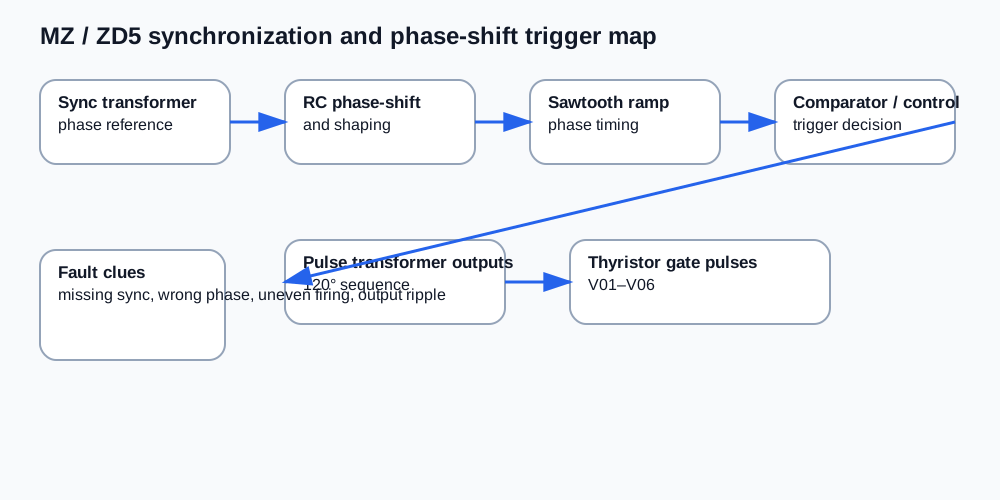
Signal path
- The synchronization transformer provides phase-related AC reference signals.
- RC shaping and phase-shift sections convert the references into timing information.
- A sawtooth ramp gives the control circuit a timing base.
- The control voltage from feedback and setpoint circuits decides when the trigger pulse occurs.
- Pulse transformers deliver isolated trigger pulses to the SCR gates.
- Changing firing angle α changes the average welding output.
Fault patterns
| Fault pattern | Likely meaning | Repair direction |
|---|---|---|
| Output current jumps or is uneven | Trigger timing or phase sequence error | Check synchronization reference, sawtooth ramp and pulse transformer outputs. |
| One SCR group does not conduct | Missing gate pulse or failed gate path | Compare gate pulses between corresponding thyristors. |
| Output cannot be regulated | Control voltage not shifting trigger angle | Check feedback input, setpoint input and phase-control amplifier. |
| SCRs overheat after board repair | Wrong trigger phase or unequal conduction | Recheck wiring, pulse transformer polarity and phase relationship. |
Service caution
A meter may confirm supply rails and basic DC levels, but it cannot fully verify trigger timing. For final diagnosis, compare trigger pulses with a scope or a phase-aware test method. Do not treat the presence of control-board power as proof that the SCR firing sequence is correct.