Circuit
MZ / ZD5 Current Feedback and Overcurrent Protection Circuit
A WelderData reference for current feedback and overcurrent protection in MZ / ZD5 thyristor welding power sources.
Database summary
The MZ / ZD5 current feedback loop measures welding current and converts it into a control signal that changes the SCR firing angle. Unlike small inverter control boards where a PWM controller drives high-frequency switches, this system controls a thyristor rectifier by shifting the firing point. Current feedback, setpoint voltage and protection logic all meet in the phase-control section.
WelderData feedback map
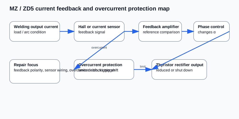
Feedback behavior
When welding current rises, the current sensor or Hall feedback path changes the feedback voltage. The amplifier compares that feedback with the current setpoint. The phase-control circuit then advances or retards the trigger pulses to keep output current near the selected value. If the current signal becomes excessive, the protection path moves the trigger pulses toward a safer condition or blocks the drive.
Some service references use a negative feedback voltage at rated current. WelderData treats such values as machine-specific calibration evidence: confirm the exact board and measuring point before applying a number to a different power source.
Repair checks
- Confirm the current sensor supply and signal return are intact.
- Check current feedback polarity; reversed sensor wiring can make regulation unstable.
- Verify the feedback amplifier output changes when current feedback changes.
- If output current is always maximum, check for missing feedback or a failed phase-control input.
- If output is weak or blocked, check whether overcurrent protection is falsely active.
- After replacing a control board, confirm trigger angle changes under setpoint and feedback changes.
Fault routing table
| Symptom | Likely section | Next check |
|---|---|---|
| Current cannot be reduced | Missing negative feedback or failed amplifier | Check current sensor wiring and feedback amplifier. |
| Current is too low | False overcurrent or wrong feedback scaling | Check protection latch, feedback voltage and setpoint path. |
| Current hunts or oscillates | Feedback compensation or phase trigger instability | Check feedback capacitors, amplifier stability and trigger sequence. |
| Overcurrent trips instantly | Sensor polarity / overcurrent threshold issue | Verify current sensor direction and overcurrent comparator input. |