Circuit
MZ / ZD5 Double-Star Thyristor Rectifier with Balancing Reactor
A WelderData reference for the main thyristor welding power source used in MZ / ZD5 submerged arc and heavy DC welding platforms.
Database summary
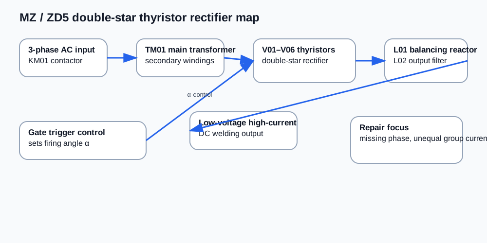
The MZ / ZD5 power source uses a controlled rectifier rather than a high-frequency inverter. The main path is three-phase input, AC contactor KM01, main transformer TM01, six thyristors V01–V06, balancing reactor L01, filter reactor L02 and the DC welding output. This architecture is suited to low-voltage, high-current welding output.
The important repair distinction is that output is controlled by the thyristor firing angle α. A fault in synchronization, trigger pulse, feedback or one thyristor group can change the output current even when the main transformer and contactor are healthy.
WelderData rectifier map
Core operating logic
The double-star rectifier behaves like two three-phase half-wave rectifier groups working together through the balancing reactor. L01 helps the two groups share load current and reduces unequal conduction between rectifier groups. L02 smooths the welding current after rectification.
The useful service relationship is that average DC output changes with the cosine of the control angle. Under load the controlled output is often represented as Ud = 1.17U2cosα. Under no-load conditions a higher factor may be used, commonly Ud = 1.35U2cosα. Treat these as functional references for understanding control action, not as a substitute for measuring the actual machine.
What L01 does
- Lets the two three-phase half-wave groups operate in parallel.
- Helps the two rectifier groups carry similar load current.
- Reduces direct-current magnetization of the reactor core.
- Supports low-voltage, high-current welding output.
- Can become a suspect when output ripple, current imbalance or group overheating appears.
Repair routing table
| Symptom | Likely section | Next check |
|---|---|---|
| One rectifier group overheats | Unequal firing or thyristor group fault | Compare gate pulses, SCR conduction and L01 connections. |
| Output current unstable | Trigger timing, feedback or reactor path | Check synchronization, phase-shift trigger and feedback signal. |
| No welding output but contactor pulls in | Trigger circuit or SCR gate drive | Do not replace the transformer first; verify gate pulses and control supply. |
| Output ripple unusually high | L01/L02 or missing phase conduction | Check reactors, thyristor conduction and phase balance. |