Repair workflow
ZX7 Series Common Fault Table for Stick / TIG Inverter Welders
A WelderData series-level diagnostic table for ZX7-315, ZX7-400, ZX7-500 and ZX7-630 style stick / TIG inverter welders. Use it to route symptoms before moving into board-level tests, tools or model-specific repair pages.
Database summary
This WelderData record summarizes a ZX7 series repair pattern rather than a single machine failure. The inverter path starts from three-phase 380V input, passes through three-phase rectification, the DC bus, IGBT high-frequency inversion, the high-frequency transformer, output rectification and filtering. The control board compares current setpoint and feedback, applies PI regulation and drives the inverter through the driver board.
Because the power stage and control loop interact, the same external symptom can have several roots. A breaker trip can come from the three-phase rectifier, IGBT module, output diode module, MOV/varistor or shorted wiring. Unstable welding current can involve phase loss, feedback wiring, bad front-panel controls, poor ground cable contact or a control-board fault. This page routes those observations into practical inspection groups.
ZX7 series main power and control flow
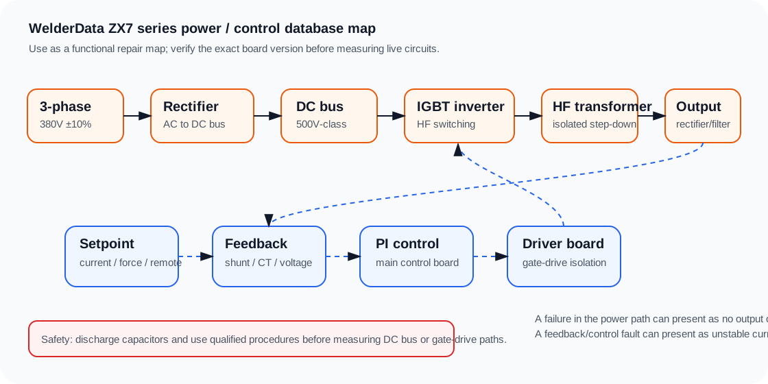
Model and output reference
| Item | ZX7-315 | ZX7-400 | ZX7-500 | ZX7-630 |
|---|---|---|---|---|
| Input | 3-phase 380V ±10%, 50Hz | |||
| Rated output power | 10.3 kW | 14.4 kW | 20 kW | 27.7 kW |
| Rated input current | 19A | 26A | 40A | 50A |
| Duty cycle | 60% | |||
| Current range | 20–315A | 20–400A | 20–500A | 50–630A |
| No-load voltage | 72 ± 8V reference | |||
| Efficiency / power factor | 89% efficiency reference, 0.95 power factor reference | |||
For output characteristic references, the stick-welding load-voltage relation is treated as U = 20 + 0.04I. The TIG relation is treated as U = 10 + 0.04I. These are reference relations for routing and calibration checks, not a substitute for manufacturer-specific test procedure.
Fault routing table
| Observed symptom | Likely groups | WelderData routing |
|---|---|---|
| Power indicator off, machine dead, fan not running | Phase loss, 2A fuse, wiring break, power transformer, air switch, fan fault | Start at input power, fuses, transformer supply and wiring before blaming the control board. |
| Rear air breaker trips during operation | IGBT module, three-phase rectifier module, output diode module, MOV/varistor, driver board, line-to-line short | Inspect the power devices and driver board together; if IGBT damage is found, also check 12Ω / 5.1Ω drive resistors and SR160-class diode parts where applicable. |
| Welding current unstable | Phase loss, panel potentiometers or switches, remote cable, poor ground cable, control board | Verify input phase and external welding cable condition before moving to setpoint and feedback circuits. |
| Current cannot be adjusted or is too high / too low | Internal wiring, shunt wire, remote cable, IGBT open, driver board, potentiometer, panel switch, 20040 module, commutation inductor, resonant capacitor | Separate display/setpoint faults from real current faults. Use shunt or external current evidence before recalibrating the board. |
| TIG does not work or no high-frequency start | Torch switch, remote line, tungsten gap, high-leakage transformer, HF board, HF return wire, main control board, 20040 module, frame capacitor board, S/T switch | Route first by process: gas/trigger, HF generation, HF return path, output enable and control-board mode logic. |
| Burns tungsten | Polarity reversed, no argon, tungsten too thin for current | Check process setup before opening the machine. |
| No argon / constant gas flow | Solenoid spring or inlet blockage, control board, broken solenoid wire, solenoid coil, AC36V transformer, torch or regulator fault | Separate mechanical valve fault from control-board drive fault. |
| No no-load voltage | 20040 diode module, main control board, stick/TIG switch, display meter, transformer, fuse, A/V switch | Check actual output first. If true output exists, inspect display/A-V switch. If output is missing, verify 36V source, voltage doubler/control path and 20040 module. |
| Fault light on | Internal temperature high, thermal relay, broken thermal wiring, control board, duty-cycle overload | Do not bypass protection. Confirm fan, airflow, thermal switch and duty-cycle condition. |
| Stick welding works but TIG does not | Main board, isolation transformer, power transformer, TIG control switch wiring | Use process-mode routing. Stick output does not prove TIG trigger, gas, HF or mode logic is healthy. |
IGBT module damage categories
Thermal / soft-switching loss
Overload output, CT board failure or reversed CT connection, RC snubber board capacitor fault, resonant capacitor failure, resonant inductor short and commutation inductor faults can destroy the intended switching condition.
Overvoltage
Turn-off spike voltage and grid-voltage fluctuation should be considered when the replacement device fails quickly or when snubber / resonant parts are abnormal.
Overcurrent
Control-board faults, broken wiring, feedback failure or incorrect drive conditions can produce excessive current stress.
Cooling failure
Loose heatsink pressure or missing thermal compound is a real repair cause, not a cosmetic issue. Device mounting must be confirmed before validation.
Calibration and service notes
- Maximum current display: the maximum current display can be set with the related current setpoint adjustment, such as W4 on applicable board versions.
- Minimum current display: minimum display adjustment may use W8 or W7 depending on board version.
- Feedback amplifier zero: the current feedback amplifier zero reference is recorded as U12(7) to the relevant ground/reference point near 0 ±2mV on applicable boards.
- Shunt signal: with current setpoint at 200A and TIG state under controlled test, some board references use shunt output targets such as 50mV for 315/400 and 30mV for 500-class machines, with board-version notes.
- Long output cable behavior: if cables are long or contact loss is high, arc force and load-voltage behavior can be misread as a board failure. Check voltage drop and cable condition.
ZX7 series routing matrix
Use this table as a first-pass series-level router before moving into a model-specific page. It does not replace board measurements; it helps choose the first board area to isolate.
| Symptom group | First evidence to collect | Likely section | WelderData next page |
|---|---|---|---|
| Breaker trips or lamp limiter stays bright | Input bridge, DC bus short, IGBT / MOSFET short, output rectifier check | Power stage or bus path | Lamp limiter tool |
| Protection / fault light on | Input phase, undervoltage, overcurrent, thermal state and driver supply | Protection feedback loop | Overcurrent page |
| No open-circuit voltage | Confirm real output first, then display path, 36V supply, OCV generation and 20040 output rectifier | Output enable or display / OCV path | No OCV page |
| Current cannot be adjusted | Potentiometer, panel harness, CA3140 / feedback amplifier, shunt reference | Current command / feedback | Current not adjustable |
| TIG has HF but no stable arc | HF cutoff logic, torch switch, gas flow, output enable and arc-voltage detection | TIG start / output transition | TIG HF start logic |
| Repeated IGBT failure | Driver bias, branch symmetry, snubber / resonant parts, CT feedback and cooling pressure | Gate drive and power-stage stress | IGBT keeps blowing |
Model-to-fault usage note
ZX7-125 / 160 / 180, ZX7-250 and ZX7-315 / 400 / 500 / 630 machines share the same broad diagnostic concept, but the board layout and voltage/current rating differ. Use the series table to route the symptom, then move to the correct model or board record before replacing parts. A small portable ZX7 may use a compact power board and a large three-phase ZX7 may add phase-loss, undervoltage and heavier driver protection circuits.
IGBT-ZX7-400 routing additions
| Symptom | First measurement evidence | Likely section | Next page |
|---|---|---|---|
| New IGBT fails immediately | Lamp limiter behavior, C-E short check, output rectifier diode-mode check, gate-drive branch comparison. | Power stage, driver, snubber or secondary loading. | IGBT-ZX7-400 repair reference |
| Fan runs but no welding output | Auxiliary rails, PWM enable, current feedback and protection state. | Control board, protection input or driver enable. | Powers on but no output |
| Protection lamp after short weld | Output diode condition, thermal switch, current feedback and shunt/CT evidence. | Secondary rectifier, cooling, feedback or overload protection. | Current display vs shunt check |
| Weak arc after repair | OCV, real current, panel command, feedback and output cable condition. | Feedback loop, output section or panel command path. | Repair methodology |
IGBT-ZX7-400 deep routing table
| Fault symptom | Measurement / inspection evidence | Likely repair area | Do next |
|---|---|---|---|
| Power trips or lamp limiter stays bright | Check bridge rectifier, DC bus capacitor, IGBT C-E, surge absorber and secondary rectifier after discharge. | Input / DC bus / inverter / secondary short. | Keep the power section isolated until the hard short is identified. |
| New IGBT fails after installation | Compare all gate branches, gate resistors, clamp diodes, snubber capacitors and output diode modules. | Driver branch, snubber, soft-switching / commutation or output load. | Return to IGBT precheck and do not repeat full-power testing. |
| Fan and display work, but no welding output | Confirm auxiliary rails, PWM enable, driver command, output diode condition and protection input state. | Control supply, PWM / driver enable, protection logic or secondary output. | Separate “no driver command” from “driver exists but output missing.” |
| Protection after a short weld | Check cooling, thermal switch, CT / shunt feedback, output cable, secondary rectifier and overload condition. | Thermal path, feedback loop, output load or real overcurrent. | Record whether protection is legitimate before changing the board. |
| Weak arc after repair | Check real welding current, open-circuit voltage, panel command, current feedback and output cable condition. | Feedback scaling, output rectifier, panel command or cable / clamp problem. | Use shunt / external meter evidence before trusting panel display only. |
| Current cannot be adjusted | Check panel potentiometer, command line, feedback amplifier, shunt / CT and control-board calibration. | Panel command or feedback path rather than power bridge. | Do not reopen the IGBT stage unless current feedback points there. |
ZX7-400 repair-step record template
| Record field | What to write | Why it matters |
|---|---|---|
| Original failure | Breaker trip, lamp limiter, no output, protection, weak arc, repeated IGBT failure. | Prevents mixing unrelated repair paths. |
| Power-off evidence | Bridge, bus, IGBT, varistor, output diode and visible burned parts. | Separates hard shorts before control-board diagnosis. |
| Driver evidence | Branch comparison, gate resistor, clamp diode, transformer / driver path and driver supply. | Protects replacement devices from hidden branch faults. |
| Feedback evidence | Panel command, shunt / CT signal, protection input and current validation. | Separates regulation faults from power-stage faults. |
| Restart evidence | Lamp limiter result, DC bus, no-load voltage, light arc and external current / shunt result. | Shows the repair survived staged validation. |
ZX7-315 / 400 / 500 / 630 PCB test-point workflow
The series fault table should now be used together with the dedicated TP1-TP16 workflow. Use it when the symptom points to PCB1 control logic, current adjustment, undervoltage sampling, overcurrent protection or display/output mismatch.
| Symptom | Test-point route | Do before replacing the PCB |
|---|---|---|
| Current cannot be adjusted | TP15 / TP16 / TP4 plus potentiometer and feedback path | Check RP1, panel harness, CA3140 current-feedback path and calibration jumper. |
| Undervoltage light on | Input voltage and phase first, then PCB1 sampling evidence | Confirm real 3-phase supply under load; threshold reference is around AC280V-300V. |
| Overcurrent light on | Power-semiconductor checks first, then PCB1/PCB2 drive evidence | Do not repeatedly restart on the full 540VDC bus. |
| Display changes but output is wrong | TP rails, command range, shunt/feedback and real output evidence | Use external current/shunt measurement before recalibration. |