Repair workflow
AC Transformer Arc Welder Common Fault Routing
A structured workflow for traditional AC transformer welders, separating input, transformer, current-control, secondary output, cable and overheating evidence.
Database summary
This workflow is for traditional AC transformer welders. It is not intended for inverter, rectifier or motor-generator machines. Use it when the main evidence is no output, weak arc, abnormal hum, overheating, current not adjustable or intermittent welding current.
The repair path is simple but important: do not jump from a weak arc directly to “bad transformer.” Older AC welders often fail through loose input connections, burned tap switches, jammed current-control mechanisms, poor welding cables, overheated secondary terminals, damp insulation or blocked ventilation.
Fault routing map
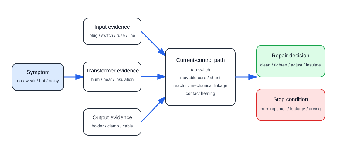
Common fault table
| Symptom | First checks | Repair interpretation |
|---|---|---|
| No hum and no output | Input plug, fuse, switch, line terminal and primary winding continuity. | Likely input/open-circuit path; do not load-test until input evidence is stable. |
| Transformer hums but no arc | Holder, work clamp, cable, secondary terminals and current-control setting. | Secondary output path or current-control issue may be present. |
| Weak arc at high setting | Cable loss, loose output terminals, tap switch contacts, movable shunt travel. | Compare evidence at machine terminals and at the workpiece. |
| Current cannot be adjusted | Tap switch, movable core/shunt, screw linkage, current scale, mechanical obstruction. | Current-control mechanism may not be changing the magnetic path. |
| Overheats quickly | Duty cycle, blocked ventilation, shorted turns clue, loose contacts, undersized cables. | Stop load testing if insulation smell or visible arcing appears. |
| Abnormal loud hum or vibration | Core clamp, loose laminations, shorted output leads, current-control shunt position. | Mechanical and magnetic evidence must be recorded before continued operation. |
| Intermittent output | Tap switch contacts, holder, cable flex points, terminal screws and internal leads. | Intermittent resistance can mimic transformer weakness. |
Stop conditions
- Insulation smell, smoke or visible internal arcing.
- Severe heating at a terminal, tap switch or output connection.
- Leakage evidence from damp windings or damaged insulation.
- Transformer noise changes suddenly under a short test load.