Diagnostic workflow
Chui Shui 500EP IGBT Failure Repair Sequence
Staged repair workflow for Chui Shui 500EP style inverter TIG machines after IGBT failure, focused on preventing repeated device destruction.
Database summary
This workflow is for a Chui Shui 500EP style machine after IGBT damage. It uses a staged repair path: visual inspection, main-loop checks, trigger-board offline test, gate-lead confirmation, HF absorption check, low-voltage current-limited test, capacitor-energy waveform test and only then resistor-load or controlled welding validation.
The purpose is to prevent the common repair mistake: replacing the IGBT module and immediately applying full bus voltage while the trigger board, gate lead, transformer, rectifier or feedback condition is still unverified.
500EP staged repair sequence
| Step | What to check | Stop condition |
|---|---|---|
| 1. Visual and fault-range estimate | Open the machine after discharge, inspect the main power area and control-board area for short, burn, carbon trace or connector damage. | Do not power the machine if the damage range is not separated into main-circuit and control-circuit evidence. |
| 2. Main loop inspection | Power switch, three-phase bridge rectifier, IGBT module, main switching transformer and secondary rectifier unit. | Any short, open, ground fault, breakdown or burned contact must be cleared with same-rated or better parts before restart. |
| 3. Trigger board offline check | Check R40–R43 2.2k protection resistors, ZD1–ZD8 1N4744 clamps and R36–R39 gate resistors. Use CN1, CN2, CN4, CN6 and CN7/CN8 as offline-test evidence. | No gate waveform, unstable trigger output or failed protection parts means the board must not be reinstalled for power testing. |
| 4. Gate-lead check | Confirm the two groups of IGBT trigger-signal leads have reliable contact and correct routing. | Poor gate-lead contact can false-trigger an IGBT and destroy the primary side again. |
| 5. HF absorption check | Offline check small HF absorption capacitors for short or loss. Treat them as protection parts for both main circuit and PCB. | Do not test the machine with suspect HF absorption capacitors connected. |
| 6. Disconnect for safe staged test | Disconnect the primary bridge output side and disconnect the HF power plug before controlled testing. | Do not mix a diagnostic power step with full HF and full main bus on the first restart. |
| 7. 30V current-limited test | Apply about 30V regulated DC to the primary input path with AC mains removed. Observe current; below about 1A class is treated as normal in this procedure. | Current above the expected class means a fault remains in the inverter path. |
| 8. Capacitor-energy waveform test | Charge filter capacitors, remove the primary rectifier output connection, then use the stored energy for a short inverter waveform observation. | Bad waveform or abnormal decay means the bridge path is not ready for load testing. |
| 9. Resistor load and calibration | Restore main wiring except HF circuit, connect a suitable resistor load and perform PCB calibration. | Do not connect full function and welding load until min/max current and overcurrent settings are recorded. |
Repair sequence map
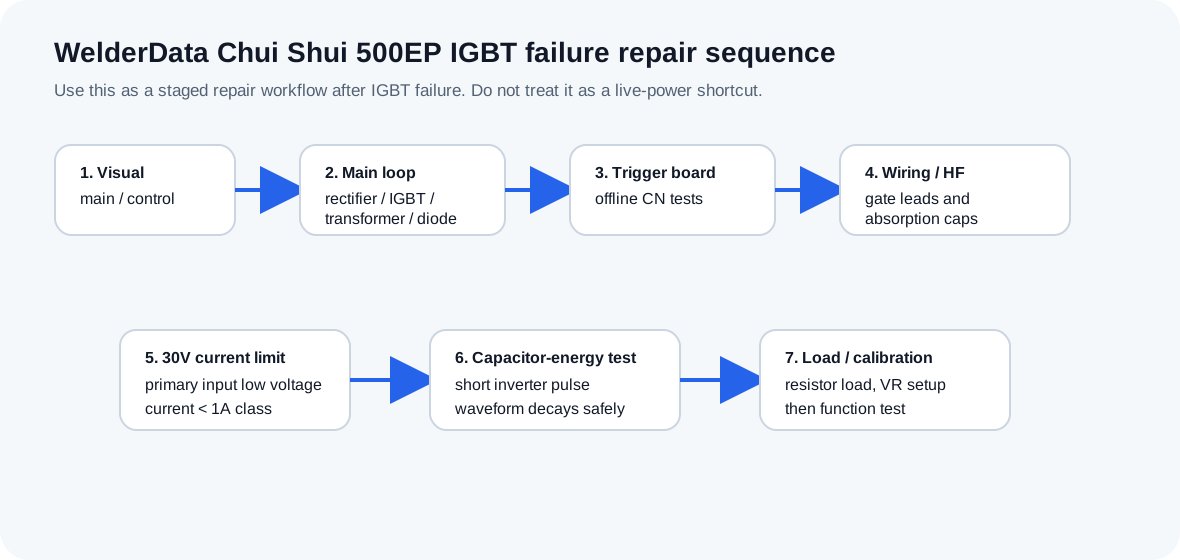
WelderData functional workflow for staged repair after Chui Shui 500EP IGBT failure.
IGBT and main component notes
| Part | Repair note | Risk if ignored |
|---|---|---|
| IGBT module | Use same model and preferably same batch pair in the same machine. Short G-E during handling to reduce electrostatic damage risk. | Different dynamic behavior or static damage can unbalance the bridge. |
| Gate resistor Rg | R36–R39 set the gate resistance. CM100DY-24H is referenced around 3.1Ω recommended / 4.7Ω used; CM75DY-24H around 4.2Ω recommended / 10Ω used. | Too-small Rg can raise switching spike; too-large Rg can slow switching and increase loss. |
| Primary bridge rectifier | Often damaged by instantaneous overcurrent when IGBT explodes. | New IGBT may see abnormal DC bus or the machine may trip before control evidence is collected. |
| Secondary fast rectifier | Module is described as using multiple FMG33 common-cathode fast diodes in parallel. | A secondary short can load the inverter and mimic primary failure. |
| Main switching transformer | 500EP transformer can short or leak to ground, including winding-to-core leakage. 500V megohmmeter evidence is recommended. | Power devices can fail again even if the trigger board is good. |
30V low-voltage current-limited test record
The low-voltage test is a risk-reduction step before full DC bus power. It is not a proof that the welder is fully repaired. Use it to catch hard shorts, wrong gate wiring and abnormal primary-side current before energizing the full inverter.
| Record item | Expected evidence | Stop condition |
|---|---|---|
| AC mains state | AC mains removed; stored energy discharged before rewiring. | Do not apply a bench supply if the original mains path is still energized. |
| Test injection point | About 30V regulated DC applied to the intended primary-side test path. | Stop if the injection point is uncertain or can backfeed the control board incorrectly. |
| Current limit | Supply current stays in a low-current class and does not climb unexpectedly. | Stop if current rises rapidly, oscillates violently or exceeds the expected low-current test range. |
| Gate evidence | CN7/CN8 and gate-lead routing were checked before this test. | Stop if trigger-board output is missing, asymmetric or lead contact is unreliable. |
| Interpretation | No hard-short evidence found under low-voltage stress. | Do not conclude full-power readiness; proceed only to the next staged test. |
Capacitor-energy waveform test record
A capacitor-energy pulse test can help observe inverter switching behavior with limited stored energy. Treat this as an intermediate waveform check between offline trigger-board testing and full-power load testing.
| Record item | What to document | What not to conclude |
|---|---|---|
| Energy source | Capacitance, charge voltage and discharge-control method used for the short test. | Do not treat a short pulse as proof that thermal behavior is safe. |
| Scope evidence | Gate waveform, transformer-primary waveform and any asymmetry between switching branches. | Do not ignore branch mismatch just because the pulse did not destroy the IGBT. |
| Protection state | Whether overcurrent, feedback or trigger-board protection reacts during the pulse. | Do not bypass protection for full-power testing without recording why it acted. |
| Next step | Move to resistor-load validation only after the pulse evidence is stable and repeatable. | Do not reconnect HF and full load in the same step after a failed power-stage repair. |