Circuit
Chui Shui EP Trigger Board IGBT Drive Calibration
Board-level reference for Chui Shui EP trigger-board offline testing, IGBT gate-drive output evidence and ordered VR calibration.
Database summary
This circuit reference covers the Chui Shui EP trigger board as a serviceable gate-drive and feedback-calibration system. The key value is the offline board test: supply the board, command enable, check CN7/CN8 trigger outputs, verify UC3706 driver behavior and adjust VR1–VR7 only in a controlled sequence.
Connector evidence table
| Connector | Function in repair record | Evidence to collect |
|---|---|---|
| CN1 | Board supply input. | Dual AC15V / AC12V class supply depending on board version and test setup. |
| CN2 | Control communication / command. | TH temperature signal, GND, CO current-feedback zero, EN enable, CC current-command signal. |
| CN3 | Temperature signal on one board version. | Check version-specific connector mapping before moving connectors between old and new boards. |
| CN4 | Shunt or feedback input on one version. | Used in offline-board test shorting procedure and feedback evidence. |
| CN5 | Primary sensor signal on one version. | Confirm old/new board connector order before installation. |
| CN6 | Primary overcurrent / AC test input. | Apply controlled AC15–20V class signal during offline test to verify protection response. |
| CN7 / CN8 | IGBT trigger output. | Scope trigger waveform and confirm branch behavior before reconnecting IGBT modules. |
Trigger board evidence map
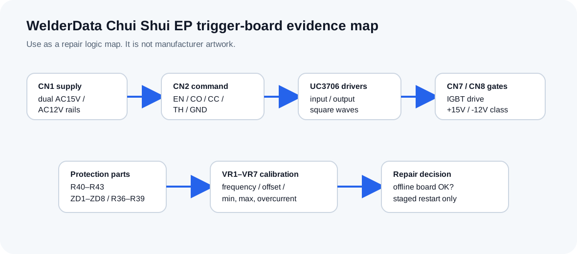
WelderData map for CN1–CN8, UC3706 gate-driver evidence and VR1–VR7 calibration.
Calibration sequence
| Control | Function | Service note |
|---|---|---|
| VR1 | Maximum voltage protection setting. | Temporarily set high during calibration only if the input voltage is confirmed normal. |
| VR7 | Working frequency. | Set with oscilloscope: 200EP about 45us, 350EP 50–55us, 500EP 55–60us. |
| VR3 | Offset / current-feedback zero. | Adjust CO indication from on to off and record the zero point. |
| VR4 | Feedback amplification. | Set feedback gain as part of the ordered sequence, not independently after full-power fault. |
| VR5 | Maximum current. | Final max-current reference is set after the overcurrent margin is checked. |
| VR6 | Overcurrent protection. | Set so protection occurs about 20A above rated current before max-current finalization. |
| VR2 | Minimum current. | Set minimum current, then revisit if max-current setting shifts the low-current point. |
Driver and protection parts
| Part group | Repair meaning | Do not continue if... |
|---|---|---|
| R40–R43 2.2k | Trigger protection resistors. | Open, burned or uneven readings exist between channels. |
| ZD1–ZD8 1N4744 | Gate/protection zener clamp network. | Any clamp is shorted or open compared with the paired branch. |
| R36–R39 | Gate resistance Rg for IGBT trigger path. | Wrong value, burned value or mismatch appears between bridge branches. |
| U6 / U7 UC3706 | Gate-driver input/output square-wave stage. | Input exists but output is absent or asymmetric. |
| T1–T4 trigger transformers | Isolated gate-drive transformer path. | Primary square wave does not transfer consistently to the gate-output connector. |
VR1–VR7 calibration record table
This table is intended as a repair record, not a generic tuning guide. Record the machine model, test setup, load condition and measured response before changing any trimmer. Do not adjust several trimmers at once after a power-stage failure.
| Control | Set after | Evidence to record | Risk if adjusted blindly |
|---|---|---|---|
| VR1 maximum voltage protection | Input supply and no-load output path are stable. | Protection threshold, test condition and whether the machine trips before output validation. | Overvoltage protection may be moved outside a safe range. |
| VR2 minimum current | Feedback zero and working frequency are known. | Minimum-current command, actual output evidence and whether arc initiation remains stable. | Low-current TIG may become unstable or fail to start. |
| VR3 current-feedback offset / zero | Feedback wiring and shunt / sensor path are confirmed. | CO indication transition point and zero-current reference. | Current feedback may be shifted, causing wrong protection or wrong display. |
| VR4 feedback gain | Offset is recorded and trigger outputs are stable. | Command-to-output relationship at low and medium current. | The machine may overreact or underreact to current feedback. |
| VR5 maximum current | Overcurrent margin and cooling state are known. | Actual output current under controlled load and clamp-meter evidence. | Maximum current can exceed safe device or transformer stress. |
| VR6 overcurrent protection | Maximum current target is understood. | Trip point and whether protection occurs above rated current margin. | Protection may fail to stop a real short or may trip during normal welding. |
| VR7 working frequency | Oscilloscope is connected to a valid timing point. | Measured period: 200EP about 45µs, 350EP about 50–55µs, 500EP about 55–60µs. | Wrong frequency can increase transformer, IGBT and rectifier stress. |
Model timing reference
The period references are useful only for Chui Shui EP-style trigger-board service. They should not be copied into unrelated inverter TIG machines.
| Model class | Working-period reference | How to use the value |
|---|---|---|
| 200EP | About 45µs | Use as a board-level timing reference after the trigger board is isolated and powered under a controlled test condition. |
| 350EP | About 50–55µs | Record the actual waveform and compare with the expected range before reconnecting IGBT gate leads. |
| 500EP | About 55–60µs | Use together with CN7/CN8 trigger-output symmetry, not as a standalone repair conclusion. |