Repair workflow
Induction Heating Power Supply Common Fault Routing
A WelderData workflow for routing industrial induction heating power-supply faults by symptom, measured evidence and power-stage section.
Database summary
Induction heating repair starts with a symptom, but the symptom must be routed through the correct section. A no-heat complaint can be caused by missing inverter drive, a protection interlock, open work coil, tank capacitor fault or disabled feedback path. Replacing power devices before checking the resonant load and cooling path is a high-risk repair.
WelderData routing map
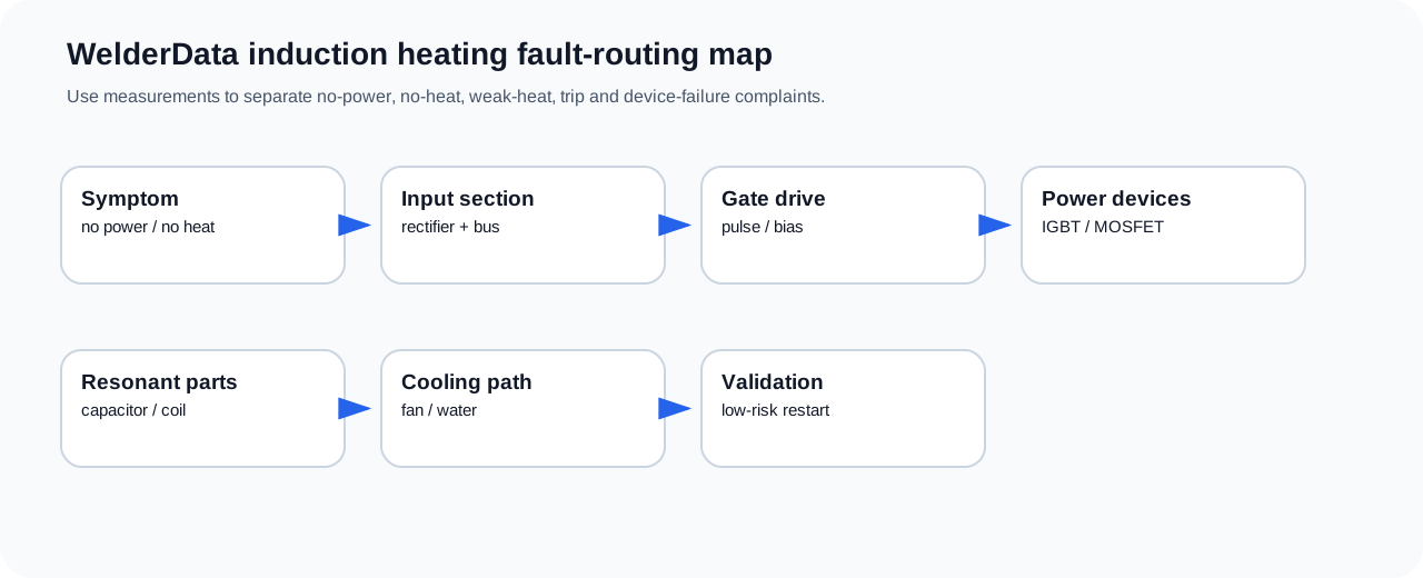
Symptom routing table
| Observed fault | Route first | Do not skip |
|---|---|---|
| Panel dead | Input power, auxiliary supply, control fuse | Confirm bus discharge before board work. |
| Panel alive, no heat | Enable command, protection input, gate drive | Check cooling / flow interlock if fitted. |
| Weak or slow heating | Work coil, resonant capacitor, frequency / feedback | Inspect high-current joints and coil coupling. |
| Trip after start | Overcurrent, tank mismatch, shorted device, cooling fault | Separate inverter short from resonant-load overload. |
| New devices fail again | Gate drive, snubber / tank capacitor, cooling, load short | Use staged restart, not direct full-power testing. |
Relation to welding-machine repair
Induction heating equipment is not an arc welder, but many repair concepts overlap with inverter welding machines: DC bus safety, IGBT / MOSFET testing, gate-driver bias, protection latch, current feedback and staged power-up. WelderData keeps it as a related industrial power-supply branch rather than mixing it into ZX7, TIG or MIG fault pages.