Diagnostic workflow
Panasonic YC-300TSP HF No-Start and SCR Phase-Loss Routing
Workflow for YC-300TSP TIG faults where high-frequency start, low OCV and SCR phase-loss evidence must be separated before replacing P-boards or thyristor modules.
Database summary
This workflow converts YC-300TSP no-HF and low-output complaints into measurement evidence. It separates the main control P-board from the HF transformer/capacitor/spark-gap path and separates low OCV from SCR phase-loss faults.
WelderData functional map
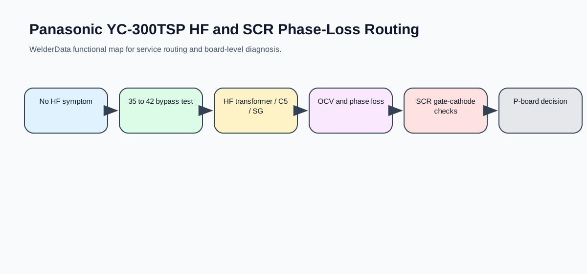
No-HF routing
| Check | Expected / clue | Next decision |
|---|---|---|
| Power fuse and torch switch cable | Fuse intact and torch switch path closes. | If open, repair the basic command path first. |
| Welding mode switch | Must not be left in stick-welding mode. | Wrong mode can mimic HF circuit failure. |
| MS2 contact path 68 to 40 | Contact should close when command is valid. | If not, route to contactor / control logic. |
| 35 to 42 bypass test | HF appears after bypass: P-board side fault. HF still absent: HF circuit fault. | Use only as a controlled diagnostic distinction. |
| HF circuit hardware | CR2 contact, HFTr, C5 and SG spark gap. | Contamination at SG should be cleaned and set near 0.7–0.9mm. |
Low open-circuit voltage and SCR checks
| Evidence | Reference | Interpretation |
|---|---|---|
| No-load output voltage | About 57V DC. | Lower value can indicate phase loss, contactor contact trouble, SCR module, protection board or P-board fault. |
| Secondary phase voltage | About 42V AC. | Use this to separate source-side phase trouble from output-side assumptions. |
| Board line-pair resistance | 8-18, 10-20, 9-19, 12-22, 11-21, 13-23 about 30–40Ω. | Open or high resistance points to the corresponding SCR/protection branch. |
| SCR gate-cathode resistance | About 30–40Ω. | Open or abnormal resistance supports SCR module replacement after wiring checks. |
CR12 countermeasure note
Frequent torch-switch operation can damage CR12 contact behavior on the P-board. Service notes describe changing the relay type, adding a zener clamp and adding capacitors to protect IC9. WelderData records this as a board-level design/countermeasure note, not a universal TIG repair rule.