Circuit
AC Square-Wave TIG Output Control
A WelderData circuit reference for separating DC output health, AC polarity switching, cleaning action and balance-control faults in AC/DC TIG welders.
Database summary
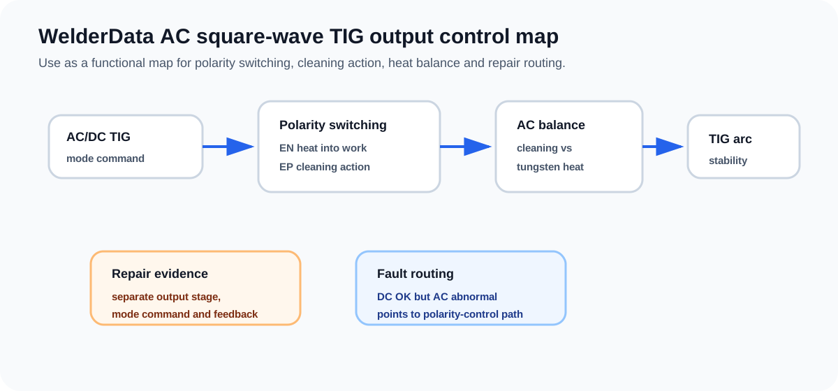
AC square-wave TIG control is used when the machine must alternate output polarity while maintaining arc stability. For aluminum and magnesium work, electrode-positive time contributes oxide cleaning, while electrode-negative time concentrates heat into the workpiece. A repair diagnosis must therefore separate the basic welding output from the polarity-switching and balance-control path.
WelderData AC TIG control map
What AC square-wave control changes
In DC TIG diagnosis, the technician mainly verifies current command, output stage, feedback and protection. In AC/DC TIG, an additional control layer changes polarity. A machine may weld in DC mode but fail in AC mode because the polarity-switching stage, drive command, mode selector or balance-control path is abnormal.
When the complaint is poor cleaning, excessive tungsten heating, unstable AC arc or AC mode not working, do not treat the fault as a generic no-output condition until DC mode and auxiliary rails have been checked.
Repair routing table
| Observed evidence | Likely route | Next check |
|---|---|---|
| DC TIG output works, AC mode does not | AC polarity-control path | Mode selector, AC output drive, polarity-switching command and related feedback. |
| AC arc starts but cleaning is poor | AC balance / polarity timing | Check balance command, setting path and whether EP interval is being generated. |
| Tungsten overheats heavily in AC mode | Excessive electrode-positive behavior or output imbalance | Check AC balance and output-stage symmetry. |
| No HF and no TIG start | Start-control path before AC balance | Check torch switch, gas timing, HF enable and protection rails first. |