Diagnostic workflow
Pulse MIG / MAG Common Fault Routing
A symptom-first WelderData workflow for pulse MIG/MAG welders, focused on deciding whether the fault belongs to the base MIG system, pulse command section, feedback loop or output stage.
Database summary
Pulse MIG/MAG faults should be routed in two layers. First confirm the ordinary MIG/MAG functions: torch trigger, gas, wire feed, voltage output and stop sequence. Only after the base platform works should a fault be routed into pulse waveform generation or pulse feedback control.
This prevents a common service error: treating every poor pulse arc as a main power-stage failure. A missing or fixed pulse can also come from mode selection, front-panel command, pulse timing, feedback signal or display/setting mismatch.
WelderData fault-routing map
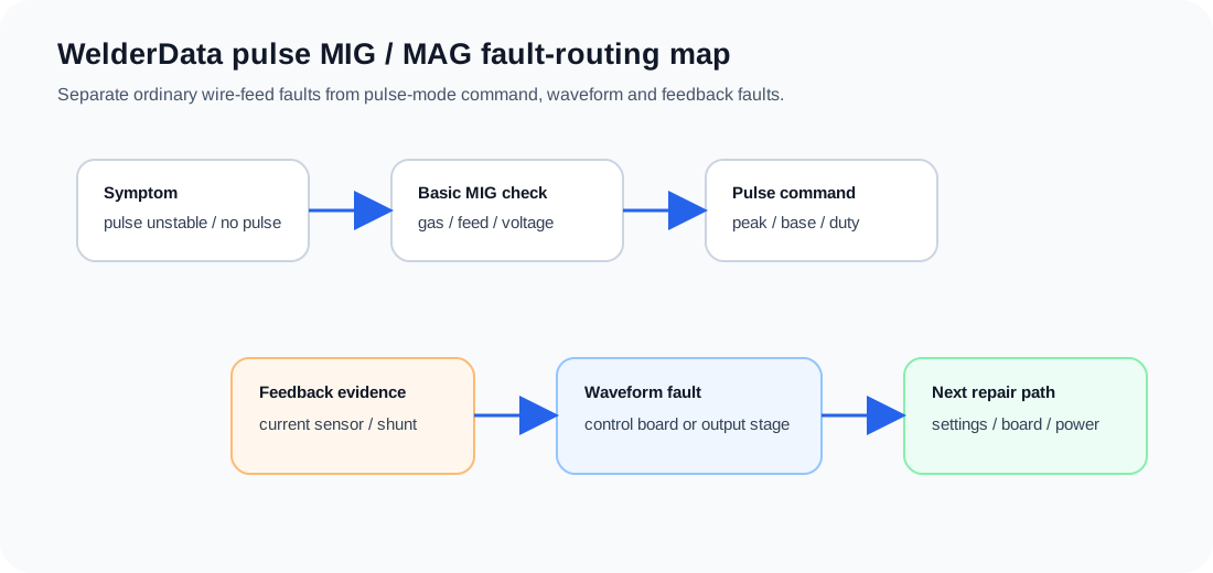
Symptom routing table
| Observed symptom | First routing | Next check |
|---|---|---|
| No wire feed, no gas, no arc | Base MIG command path | Torch switch, feeder harness, control power and enable relay. |
| Normal MIG output, no pulse action | Pulse command / mode selection | Pulse mode switch, setting circuit, display/command path and timing section. |
| Pulse rate fixed or does not follow setting | Pulse frequency command | Frequency control circuit, front-panel potentiometer/encoder and control-board input. |
| Pulse arc unstable but base welding works | Feedback / waveform regulation | Current feedback, voltage feedback, shunt evidence and waveform command. |
| High heat input despite low setting | Peak/base/duty mismatch | Duty command, base-current command and feedback response. |
| Pulse display changes but output does not | Command-to-output break | Control board output, driver enable and power-source response. |