Bench evidence
Welding Machine Component Testing Guide
A practical component-testing route for welding-machine repair. The diagrams are code-redrawn SVGs, not scanned page images.
Code-redrawn diagrams only
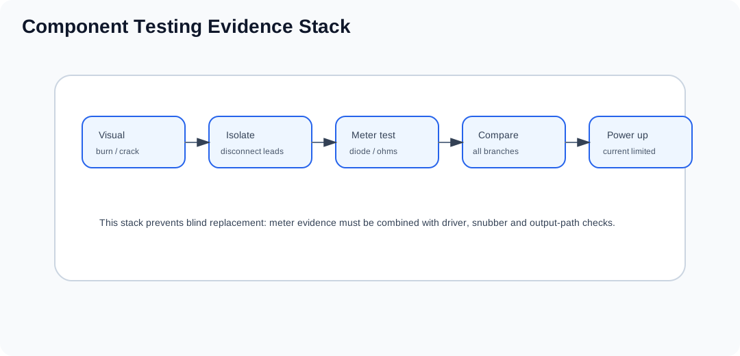
This page no longer uses scanned page images. All component figures are redrawn as lightweight SVG diagrams with English labels. Detailed procedures are carried in searchable HTML tables.
Quick decision table
| Part | Normal evidence | Reject evidence |
|---|---|---|
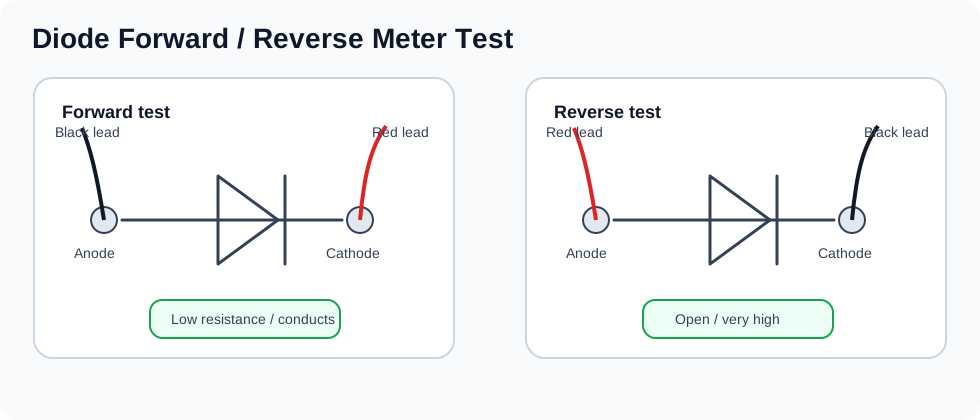
| Single diode | Conducts in one direction and blocks in the reverse direction. | Zero both ways or open both ways. |
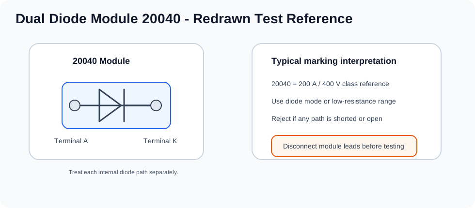
| Dual diode module | Each internal diode path behaves consistently. | Any shorted or open path means the module is not reliable. |
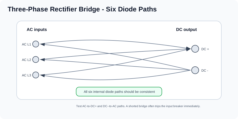
| Three-phase bridge | All six AC/DC paths show consistent diode behavior. | A shorted path often trips the input breaker immediately. |
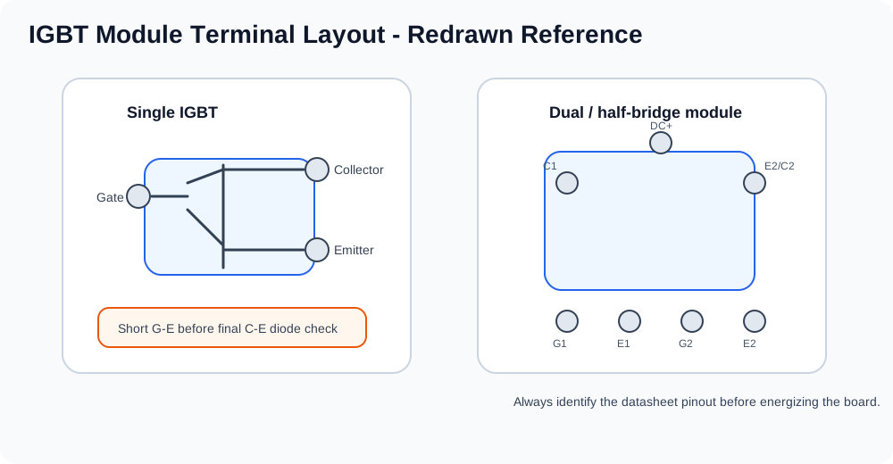
| IGBT module | Gate charge changes C-E behavior; built-in diode remains directional. | Permanent C-E short, no response, or uneven parallel branches. |
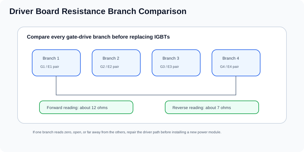
| Driver board | All gate-drive branches are close to the expected resistance values. | One branch reads zero, open, or far from the others. |