Power semiconductor test
Welder IGBT Module Testing
Use this page when an inverter welder trips the breaker, blows IGBTs, or has no output after a power-stage fault.
Bench-test sequence
| Step | Expected action | Failure clue |
|---|---|---|
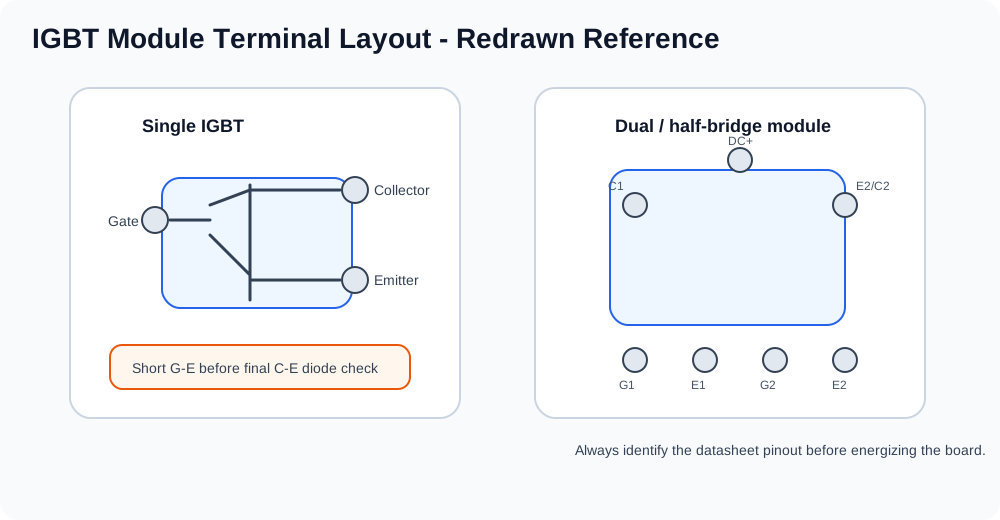
| 1. Identify the module | Confirm whether the part is a single IGBT, dual module, or multi-unit module. | Do not assume pinout from a similar package. |
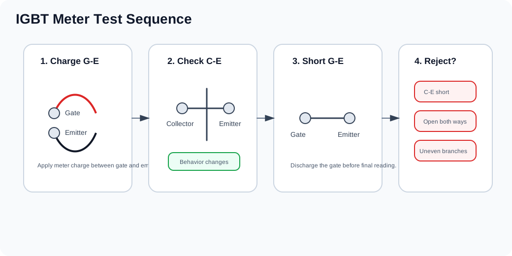
| 2. Charge G-E | Use the meter to charge the gate-emitter path according to the module type. | No change in C-E behavior can indicate a damaged gate structure. |
| 3. Check C-E | A healthy module changes behavior after gate charge and returns after G-E discharge. | A permanent C-E short means the module is failed. |
| 4. Short G-E | Discharge the gate before final diode and isolation checks. | Floating gates can give misleading readings. |
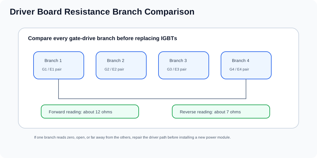
| 5. Compare branches | Parallel or paired branches should be consistent. | One abnormal branch points to module or driver imbalance. |
Before installing a new IGBT
Do not stop at the failed module. Check the driver board, gate resistors, clamp network, snubber components, DC bus, output rectifier and load path. Replacing only the IGBT often leads to repeat failure.