Fault
ZX7-250 No 510V DC Bus: Power Board, Bridge Rectifier, Capacitor and Relay Checks
A ZX7-250 power-board fault guide for machines where the high-voltage DC bus does not reach the upper inverter board.
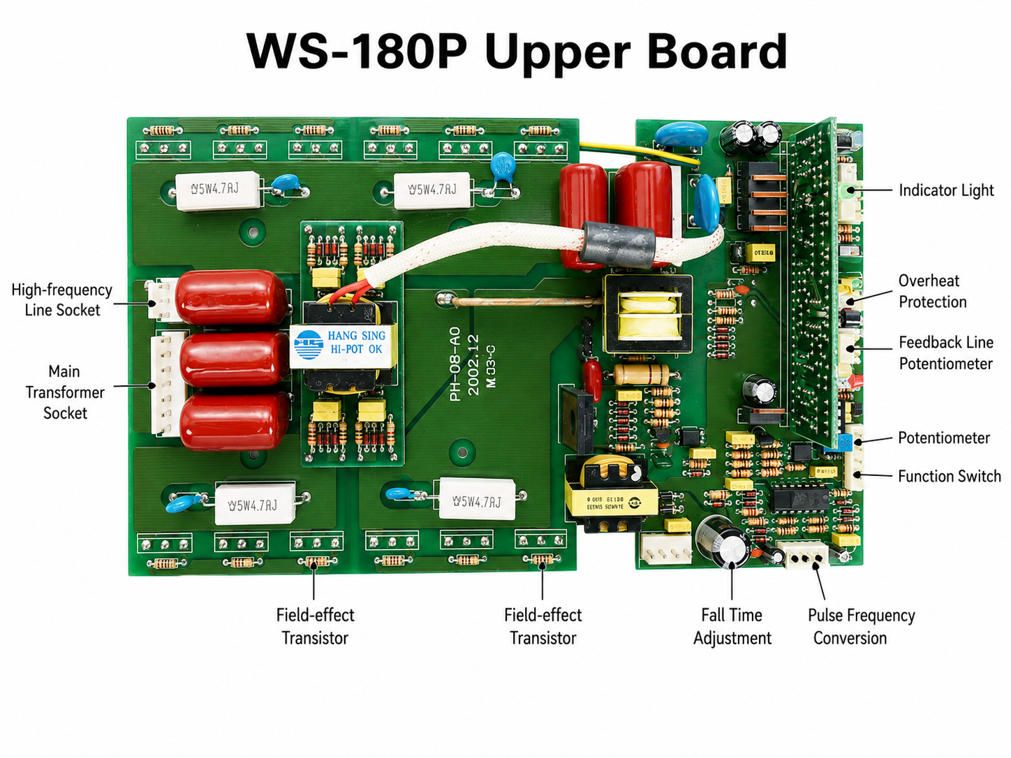
WS-180P upper board annotated reference
This annotated board view is intended for orientation before board-level checks. Use it to identify the high-frequency line socket, main transformer socket, MOSFET area, feedback controls, protection input and timing/frequency adjustment areas before measuring or replacing parts.
What the 510V check tells you
The 510V DC bus check is a useful boundary test. If a ZX7-250 has fan activity but no welding output and the high-voltage connector to the upper inverter board does not show the expected DC bus, the repair should not start with PWM chips or IGBTs. The missing voltage points back to the input power board and its enable path: bridge rectifier, electrolytic capacitors, 24V relay, connector and the traces between them.
Power-board path

Common measurement table
| Measurement point | Expected behavior | Repair direction |
|---|---|---|
| AC input to power board | Present and stable | Input cable, switch, breaker or wiring fault |
| Bridge rectifier output | DC bus begins forming | Bridge rectifier / silicon bridge may be open or shorted |
| Capacitor bank | Charges and holds bus voltage | Open capacitor, bad solder or failed capacitor bank |
| 24V relay / enable stage | Relay closes when control condition is satisfied | Relay coil, driver or control supply path fault |
| High-voltage connector | About 510V DC reaches upper board | Connector, relay contact, bridge/capacitor path or trace fault |
Repair logic
A missing 510V bus should be treated as an upstream energy-transfer problem. Check the high-voltage path before testing the driver board. If the bridge rectifier is shorted, the machine may trip the breaker. If the bridge or relay path is open, the machine may appear partially alive but cannot deliver welding output. If the capacitor bank is damaged, the bus may be low, unstable or unsafe under load.
Practical checks
- Inspect relay solder joints and relay contacts for heat or arcing.
- Check whether the relay coil receives the required control voltage.
- Measure the bridge rectifier for shorted or open junctions after discharging capacitors.
- Inspect electrolytic capacitors for bulging, leakage or cracked solder joints.
- Check the connector from the power board to upper board for burnt pins or looseness.