Model reference
Panasonic YM-500CL4HGE Long-Distance CO2 Welder Repair Reference
Model-family page for the Panasonic YM-500CL4HGE long-distance CO2 welding platform, with service notes for carrier control, feeder indicators, Q34 motor drive and moisture-sensitive feeder PCB faults.
Database summary
The YM-500CL4HGE is a Panasonic long-distance CO2 welding platform designed for work sites where the feeder may be far from the power source. Its welding power section follows KR-style thyristor rectifier principles, but the feeder command system is different: control information is carried through a carrier-control path rather than a conventional multi-core control cable.
WelderData treats this machine as a separate service family because symptoms can originate in the welding source, the feeder-side control board, the carrier-control signal path, the torch-switch wiring, the feeder motor chopper stage or moisture damage inside the feeder unit.
WelderData functional map
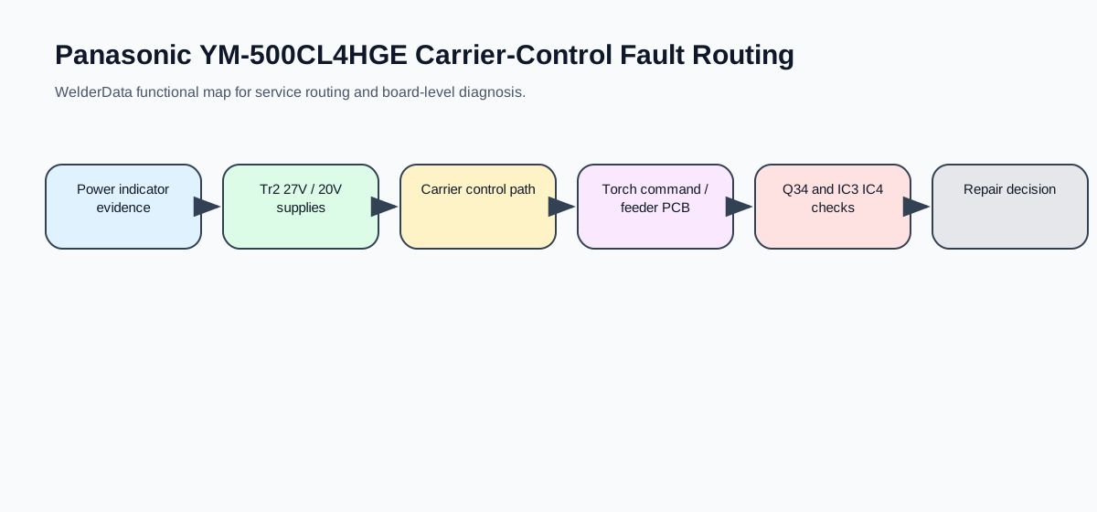
Why this platform is different from ordinary KR-style CO2 welders
| Feature | Service implication | What to check first |
|---|---|---|
| No conventional control cable for long-distance operation | A feeder fault may not look like a normal six-core cable fault. | Power-source indicator, feeder indicator and carrier-control response. |
| Carrier-control signal transmission | Command fidelity depends on the carrier path and feeder PCB condition. | Torch command, feeder PCB supply and response at the power source. |
| Transistor chopper wire-feed drive | Motor-speed faults may come from the chopper transistor stage, not only from the motor. | Motor power line, feeder load and Q34 protection evidence. |
| Motor back-EMF feedback | Wire-feed instability can come from the feedback path even when the motor runs. | Motor harness, feedback evidence and feeder PCB moisture/contamination. |
Indicator-based fault routing
| Symptom | Likely area | Repair route |
|---|---|---|
| Power-source and feeder indicators both off. | Input phase, power switch, Fu1 or Tr2 control transformer. | Check input supply and fan behavior before opening feeder PCB diagnosis. |
| Only feeder indicator is off. | Tr2 27V feeder supply, circuit protector, protector wiring or feeder PCB. | Record whether the power-source indicator remains normal; then check the feeder-side supply path. |
| Only welding-source indicator is off. | Tr2 20V source-side supply or source PCB. | Do not condemn the feeder board until source control power is confirmed. |
| Torch switch pressed and no action occurs. | Torch switch, switch wiring or feeder PCB command input. | Separate trigger input evidence from main contactor / output evidence. |
| Abnormal lamp is on. | Duty overload, output overload, thermal relay Th1/Th2 or thermal relay wiring. | Check thermal state and relay continuity before replacing the control PCB. |
| Circuit protector trips. | Short between feeder-related lines and work/ground return. | Inspect gas connector, CC fitting, torch-switch line and wire-feed motor power line. |
Feeder P-board fault notes
The feeder board ZUEP1216 uses Q34 as the wire-feed motor drive transistor. The service material links Q34 failure to a short between the wire-feed motor power line and the workpiece return. A protective diode across the Q34 D-S path is used as a countermeasure so that the circuit protector trips before Q34 is destroyed.
IC3 and IC4 faults are associated with rain or moisture exposure in the feeder unit. If the feeder box is wet, do not immediately replace the power source board. Dry and inspect the feeder box, control panel switches, carrier-control wiring and connector area first.