Diagnostic workflow
Panasonic KR CO2 Welder Typical Fault Routing
Symptom-first diagnostic workflow for KR-style CO2/MIG welders, covering torch command, feeder cable, remote box, P-board, SCR output and weld-quality clues.
Database summary
Panasonic KR-style CO2 welders often fail at the boundary between the torch switch, six-core feeder cable, remote control box, P-board, wire-feed motor, SCR module and gas circuit. This diagnostic page routes the common field symptoms before a technician replaces the P-board or power module.
The workflow is written for repair evidence collection. It is not a substitute for the exact factory manual for a specific serial number, but it captures the repeated KR fault patterns that are useful across similar CO2/MIG platforms.
Panasonic KR typical fault routing map
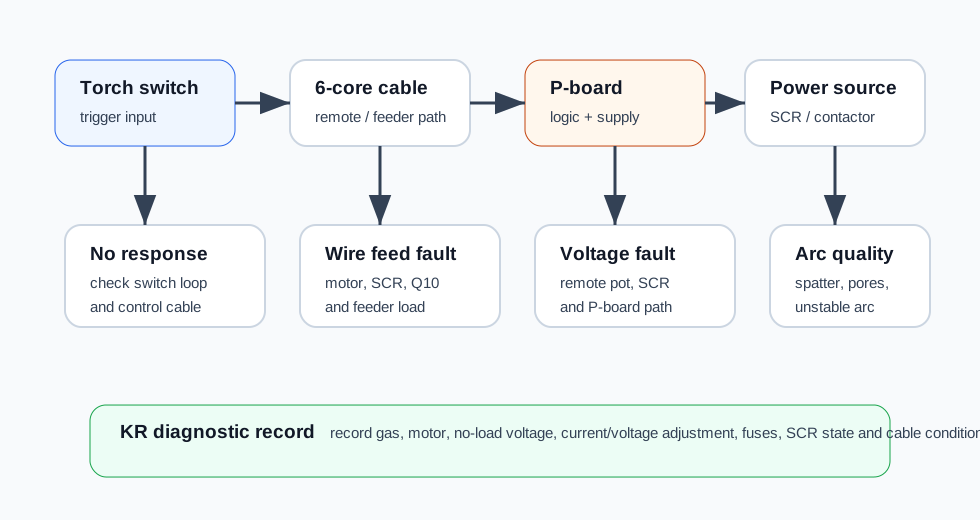
WelderData routing map for KR-style CO2 welder symptoms: trigger response, feeder line evidence, P-board logic, SCR output and arc quality.
First checks before board replacement
| Check | Why it matters | Repair decision |
|---|---|---|
| Remote box current and voltage knobs | Confirms whether the no-load voltage and feeder speed are responding to user command. | If neither command responds, inspect control cable, remote pot and P-board command path before the power stage. |
| Torch switch loop | A failed switch loop can produce no no-load voltage and no wire feed. | Unplug and test the switch loop instead of assuming the main PCB has failed. |
| Six-core feeder cable | Cable damage can separate gas, wire-feed motor, jog and setting faults. | Use the feeder table and pin continuity checks before replacing feeder motor or P-board. |
| Control transformer primary and secondary | KR troubleshooting uses primary 380V class evidence and secondary control supplies such as 200V / 20V paths. | Loss of control power must be resolved before SCR or feeder conclusions. |
| SCR module and no-load voltage | Low no-load voltage or voltage-setting failure may be caused by SCR module, P-board command or input/source evidence. | Check SCR anode/cathode/gate evidence and command path together. |
Typical KR symptoms and routing
| Symptom | Likely section to inspect first | Notes |
|---|---|---|
| Press torch switch: no no-load voltage and feeder does not run | Torch switch loop, feeder cable, control transformer, P-board start path. | Do not start from the main transformer until the trigger and control-power path are proven. |
| Abnormal indicator lights after welding for a while | Duty cycle, thermal state, fan/cooling path, overload condition. | Separate real overheating from false protection input or control-board detection error. |
| Welding current is out of adjustment | Remote current potentiometer, six-core cable, P-board control path and feeder-speed command. | In CO2/MIG systems, current tendency is strongly tied to wire-feed speed. |
| Current meter display differs from real current | Meter circuit, shunt/current sampling path and calibration evidence. | Compare with an external meter before adjusting the board. |
| Welding voltage is out of adjustment | Remote voltage potentiometer, control cable, P-board voltage command and SCR module. | Confirm whether the no-load voltage follows the voltage setting. |
| Wire feeds and no-load voltage exists, but arc does not start | Output cable, work return, contact tip, torch, wire path and output power evidence. | This is not the same as a feeder start failure. |
| Press torch switch and FU2 8A fuse blows immediately | Wire-feed motor load, Q10 brake transistor path, feeder SCRs and control cable short. | Inspect feeder resistance and cable water damage before fitting another fuse. |
| No manual wire feed, but wire feeds during welding | Manual jog switch and jog circuit. | Do not replace the motor if welding feed is normal. |
| Wire feed unstable | Guide liner, SUS guide cap alignment, feeder roller wear, liner blockage, P-board / feeder drive. | Mechanical feeder faults should be cleared before board diagnosis. |
| Wire feeds without pressing the torch switch | Torch switch short, control cable short, P-board logic fault. | Also consider IC5 / R245-type failures where output and feed appear without a valid command. |
| Gas heater does not work | Heater supply, gas-heater fuse/path and related wiring. | Separate gas heating from gas-valve flow control. |
| Heavy porosity in weld bead | Gas supply, CO2 purity, gas flow path, torch/gas leak, welding condition. | Do not treat porosity as a power-board fault first. |
| Power switch immediately blows 5A fuse | Control power, fan/auxiliary loads, transformer and shorted downstream circuit. | Use resistance checks before repeated power-up. |
| Low no-load voltage | Three-phase input, SCR module, main transformer secondary and P-board output command. | Record the no-load voltage and whether adjustment changes it. |
| Excessive spatter | Current/voltage matching, grid fluctuation, SCR output, P-board command, CO2 purity, contact tip / roller / wire diameter match. | Weld-quality evidence must be separated from control-board faults. |
| Crater-fill enabled but no working wire feed or no self-hold | Crater-fill switch state, remote box, stop-sequence logic and P-board command path. | Check crater-fill mode before replacing feeder hardware. |
KR current and voltage adjustment measurement table
Current and voltage faults should be split into command, cable, P-board and output-stage evidence. In KR-style CO2 welders, welding current behavior is closely tied to wire-feed speed, while welding voltage is routed through voltage command and SCR output control.
| Fault pattern | Check first | What the result means |
|---|---|---|
| Welding current cannot be adjusted | Six-core control cable continuity, remote current potentiometer and P-board current-command path. | If remote command is missing, do not diagnose the SCR output first. If command is present but feed/current does not respond, move toward P-board and feeder drive evidence. |
| Current meter differs from real current | Output terminal bolts, work return, CT / current feedback path and meter circuit. | Loose output hardware and poor return can make the displayed current misleading. Compare with external current evidence before recalibration. |
| Welding voltage cannot be adjusted | Six-core control cable, remote voltage potentiometer, P-board voltage command and SCR module. | If no-load voltage does not follow the voltage setting, isolate command-path evidence from SCR module evidence. |
| Current knob response feels non-linear | Remote current potentiometer and feeder/current command circuit. | Current-command response can behave differently from voltage-command response; record command evidence instead of judging only by knob position. |
| Voltage knob response should be smooth | Remote voltage potentiometer and voltage-command line. | A discontinuous or dead region points toward pot, cable or command-line fault before SCR replacement. |
Wire feeds and no-load voltage exists, but no arc starts
This fault is especially easy to misroute. When wire feed and no-load voltage are present, the start failure may be outside the P-board.
| Evidence | Check | Decision |
|---|---|---|
| Wire feeds normally and no-load voltage is present | Output cable, work return clamp and workpiece connection. | A broken output path or missing return can prevent arc start even when the control board is working. |
| Arc start fails on dirty work | Oil, rust, paint, scale or poor contact at the weld path. | Clean the work area before internal board diagnosis. |
| Simple synergic / individual setting mismatch | Mode switch or remote voltage setting. | Wrong voltage setting can make the start appear like a power-source fault. |
| Contact tip / wire path abnormal | Contact tip, liner, wire diameter and feed roller match. | Mechanical feed and contact faults should be cleared before P-board replacement. |
5A fuse blows at power-on
When the 5A control fuse opens immediately after the power switch is turned on, isolate control-power loads before repeated power-up.
| Possible section | Check | Repair interpretation |
|---|---|---|
| Control transformer secondary load | Disconnect downstream secondary loads and test whether the transformer can run unloaded. | If the fuse holds unloaded, the downstream control circuit or auxiliary load is shorted. |
| Cooling fan winding | Resistance / insulation check and mechanical rotation check. | A shorted fan winding can appear as a power-input fault. |
| Magnetic contactor coil | 500KR about 150–160Ω, 350KR about 345Ω, 200KR about 483Ω. | An abnormal coil resistance supports contactor-coil replacement before deeper P-board diagnosis. |
| Control wiring short | Inspect harness, connector, fuse holder and previous service work. | Miswired or damaged control wiring can repeatedly blow the 5A fuse. |
Low no-load voltage routing
Low no-load voltage on KR-style machines can be caused by input-side, SCR-side, contactor-contact, transformer-secondary or P-board command faults.
| Step | Measurement evidence | Meaning |
|---|---|---|
| Confirm three-phase input | Rear-panel three-phase input in the 380V ±10% class range. | Phase loss or input sag must be corrected before SCR or P-board conclusions. |
| Check SCR modules | Anode/cathode/gate evidence and whether both module groups respond. | A failed SCR module can reduce no-load output or make voltage adjustment abnormal. |
| Check contactor contacts | Burned, high-resistance or uneven contacts. | Bad contacts can lower transformer primary drive even when the coil pulls in. |
| Measure main transformer secondary | 500KR about 50±1V; 350KR about 40.7±1V; 200KR about 28.2±1V. | If secondary voltage is normal but output is low, continue toward SCR/output path. If secondary is low, trace input/contactor/transformer path. |
| Check P-board command | Voltage command and SCR firing evidence. | If command does not reach the SCR firing path, low OCV may be control-related rather than transformer-related. |