Model reference
Rotary DC Arc Welders Repair Reference
A WelderData reference for motor-generator DC arc welders, focused on the repair evidence that separates the drive motor, generator field, brush/commutator system, output reactor and welding leads.
Database summary
Rotary DC arc welders are older welding power sources that use a rotating electrical machine rather than a static rectifier or inverter. A motor drives a DC generator. Welding current is controlled through excitation, field regulation, magnetic characteristics and the output circuit.
For repair work, the important point is to avoid treating every weak arc or no-output condition as a single “generator failure.” The motor may run correctly while the field circuit is open, the brushes may lose contact, the commutator may spark, the current rheostat may be open, or the welding leads may waste the output before it reaches the arc.
Functional map
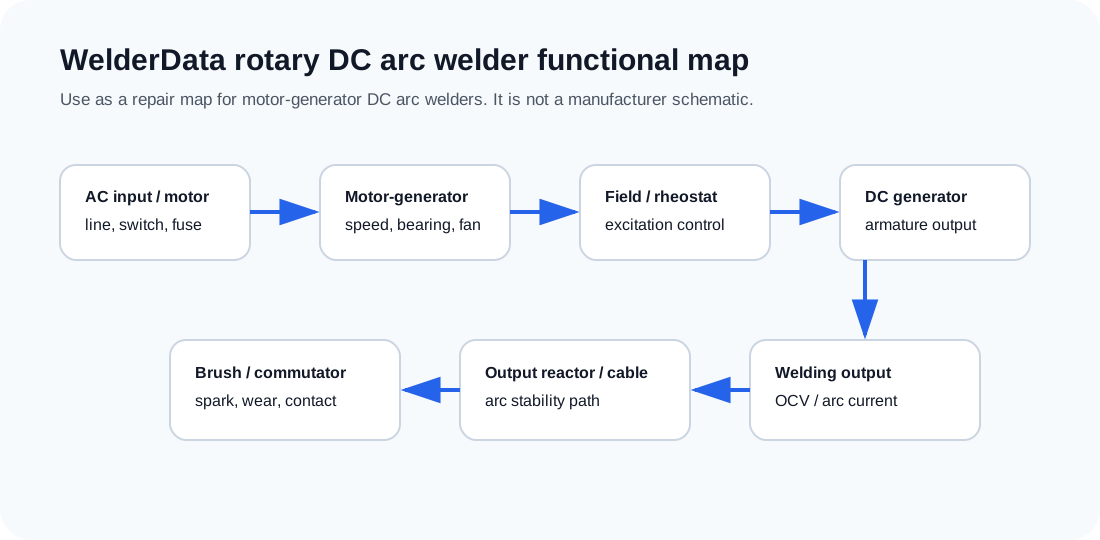
Major sections to separate
| Section | Evidence to collect | Repair interpretation |
|---|---|---|
| Input motor | Line voltage, switch, fuse, starter/contact, motor rotation and abnormal noise. | If the motor does not reach speed, output diagnosis is premature. |
| Field excitation | Field winding continuity, current-control rheostat, open leads and field supply path. | Motor may run normally but DC welding output remains weak or absent. |
| Brush / commutator | Brush wear, spring pressure, commutator surface, sparking and carbon dust. | Poor contact can cause unstable arc, heat and low output. |
| DC generator / armature | Open-circuit voltage, load response, overheating, vibration and bearing condition. | Generator-side evidence must be separated from cable or work-return loss. |
| Output circuit | Output reactor/choke, welding cable, holder, clamp and work return. | Loose or overheated output connections can mimic generator weakness. |