Model reference
WSM-400DN Pulse TIG Welder Reference
A WelderData model record for microcomputer-controlled pulse TIG welders, focused on service routing between pulse command, current feedback, HF start, gas timing and output-stage response.
Database summary
WSM-400DN-style pulse TIG welders add a digital or program-controlled pulse layer above the normal TIG current loop. A repair record should therefore separate basic DC TIG output from pulse behavior. If non-pulsed TIG current is stable but pulse mode is incorrect, the first checks should move toward pulse command, display setting, parameter storage, feedback scaling and the current-loop interface instead of replacing the main output devices.
WelderData treats this platform as a bridge between conventional TIG control and digital welding power-source diagnosis.
Service routing table
| Symptom | Likely section | Next check |
|---|---|---|
| HF and gas work, but pulse has no effect | Pulse command or parameter path | Verify pulse enable, peak/base setting, frequency/duty command and panel-to-control signal. |
| Pulse display changes but output current does not | Feedback/current-loop interface | Confirm real output with a shunt or external meter before adjusting display trim. |
| Machine starts then stops in pulse mode | Protection or command conflict | Check auxiliary rails, overheat input and feedback plausibility. |
| Normal TIG fails before pulse is enabled | Base TIG system | Check torch switch, gas valve, HF start, 24V/20V/15V rails and main current loop first. |
WelderData model routing map
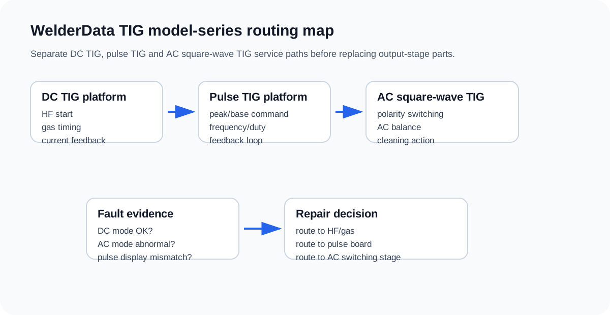
This map keeps WSM-style pulse checks separate from AC square-wave and compact AC/DC inverter checks.