Protected IGBT driver cornerstone
M57962AL IGBT Driver: Fault Output, Gate Voltage and Welder Repair
A measurement-first reference for deciding whether the module is damaged, protection is correctly tripping, or the external gate and power stage remain unsafe.
First five-minute check
What this page is for
Use this reference when an inverter welder uses an M57962AL-style protected IGBT driver and you see no gate pulse, a fault line that will not reset, a brief output pulse followed by shutdown, weak positive or negative gate bias, or a replacement IGBT that fails again. The module must be diagnosed as part of a complete gate-drive and protection system.
Why “no gate pulse” is not one diagnosis
A protected gate-driver module can remove its output because the input command disappeared, the isolated supply fell below the usable range, a collector-side short-circuit signal was detected, the fault latch is active, an external reset/enable condition is missing, the output is overloaded, or the driver module itself is damaged. Replacing the module from a single static reading can hide the original fault and destroy the new part.
In a welder, the fault may originate outside the driver board. A shorted output rectifier, saturated transformer, current-feedback error, bus overvoltage, wrong IGBT substitution, poor thermal mounting or a damaged snubber can create real collector stress. The driver then trips correctly. That protective trip must not be misread as a failed module.
Real-world visual identification reference
Use this reconstructed visual to recognize the general package shape, pin-one orientation and the kind of board area where the device is commonly found. It is a visual identification aid, not proof that a particular welder uses the same package, marking or surrounding components.
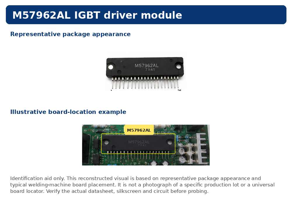
Before probing, confirm the actual device marking, package, board silkscreen and manufacturer datasheet. The board-location panel is illustrative and must not be treated as a universal component locator.
Functional terminals to identify on the actual board
| Functional group | Evidence to collect | Typical false conclusion |
|---|---|---|
| Isolated driver supply | Positive rail, negative turn-off rail if used, local reference, ripple and collapse during a pulse command. | “The module is dead” when the isolated DC/DC supply or decoupling capacitor has failed. |
| Logic/PWM input | Input amplitude, polarity, pulse width and continuity through the connector or optocoupler. | “The output stage failed” when the PWM controller, enable or isolation path never sends a valid command. |
| Gate output | Turn-on level, turn-off level, rise/fall shape and comparison with the parallel branch. | “The waveform is good” based only on an unloaded module pin while the gate resistor or connector is open. |
| Short-circuit sensing | Collector-side sensing path, high-voltage diode, delay capacitor/resistor and reference return. | “The protection is nuisance tripping” when a real collector short or current path exists. |
| Fault output | State at idle, state after trip, reset behavior and whether the control board acknowledges it. | “The PWM chip is not starting” when a latched driver fault is blocking permission. |
| Soft shutdown / reset | Controlled gate discharge, reset timing and repeatability after power cycling. | “The IGBT is low quality” when hard turn-off creates destructive overvoltage. |
Important: package pin numbers and exact thresholds must be checked against the original manufacturer datasheet and the board schematic. This page intentionally organizes repair functions rather than publishing an unverified universal pinout.
Trip command or damaged driver?
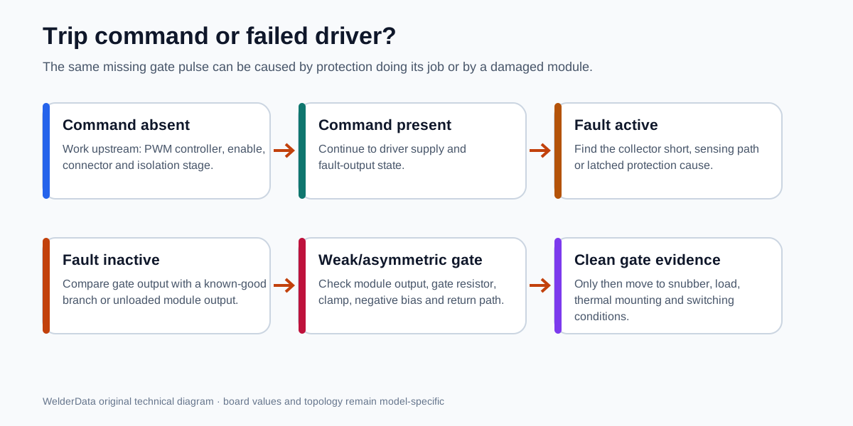
| Observation | Interpretation | Next action |
|---|---|---|
| No input command | The driver has nothing to reproduce. | Trace PWM, shutdown, connector, optocoupler and enable logic upstream. |
| Command present; driver supply absent or collapsing | Driver behavior is not valid under an unstable supply. | Repair isolated supply, rectifier, decoupling and local load first. |
| Command and supply present; fault output active | Protection is requesting shutdown or the fault path is stuck. | Inspect IGBT/collector short evidence, sensing parts and latch/reset route. |
| Fault inactive; output weak or asymmetric | Module output stage, gate network or negative-bias path may be damaged. | Compare with a known-good branch using the same probe setup. |
| Gate output good at module, bad at IGBT | The external gate branch is open, resistive or clamped. | Check series resistor, fast diode, zener/TVS, G-E resistor and connector. |
| Gate waveform good; IGBT fails under load | Move beyond the driver. | Check dead time, snubber, transformer, output rectifier, load short, cooling and substitution. |
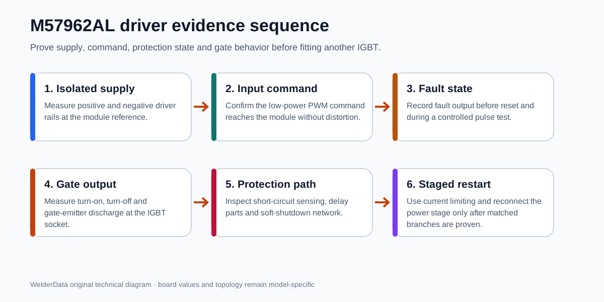
Safe staged measurement order
- Discharge and verify the DC bus before resistance tests. Remove the failed IGBT or isolate the power branch if it is shorted.
- Check gate-emitter resistance, series gate resistor, clamp network, connector and return path with power off.
- Power only the control/driver section where the board design permits. Confirm isolated positive/negative rails and ripple.
- Confirm the command input and fault state without the main IGBT conducting high bus energy.
- Compare the gate output of all parallel or complementary branches with the same probe reference, attenuation and time scale.
- Prove soft shutdown and reset behavior. Do not bypass protection to force an output.
- Install matched power devices only after snubber, current feedback, output rectifier and thermal mounting checks are complete.
- Use a lamp limiter or other model-appropriate current-limited startup, then move through no-load and controlled-load validation.
Stop conditions before another IGBT is installed
- Stop if the gate branch is not symmetrical with its known-good counterpart.
- Stop if the negative turn-off bias is missing on a design that requires it.
- Stop if the fault line is active and the causal collector/current path has not been identified.
- Stop if a gate resistor, clamp diode, sensing diode or soft-shutdown part is open, burnt or out of tolerance.
- Stop if the bus, transformer primary or secondary rectifier still shows short-circuit evidence.
- Stop if the driver supply collapses when pulses begin.
- Stop if IGBT type, gate charge, voltage/current rating, switching speed or internal diode arrangement is not verified.
Related WelderData records
Technical scope and source policy
M57962AL is treated here as a protected IGBT gate-driver module with command, gate-drive, short-circuit protection, fault and controlled shutdown functions. Exact terminal numbering, supply values, timing and protection thresholds remain device- and board-specific; verify the original Mitsubishi/Powerex documentation and the actual circuit before probing or substitution.
The diagrams are original WelderData repair maps. They do not reproduce a manufacturer drawing or claim that every welder uses the same pin assignment. Last technical review: July 13, 2026.
Related repair map
Follow the evidence path from symptom to measurement, circuit and repair case.