Circuit
Soft-Switching Inverter Arc Welder Main Loop
Phase-shift full-bridge, resonant-capacitor and saturable-inductor reference for soft-switching inverter arc welders and repeated IGBT failure diagnosis.
Database summary
A soft-switching inverter arc welder uses the energy in leakage inductance, resonant capacitors and controlled phase shift to reduce switching stress in the bridge. In a repair database this matters because a repeated IGBT or MOSFET failure may be caused by the commutation network, not by a defective replacement device.
This WelderData reference covers an improved phase-shift full-bridge arc-welding power source. It is written as a repair interpretation page, not as a design-calculation manual.
Functional main-loop map
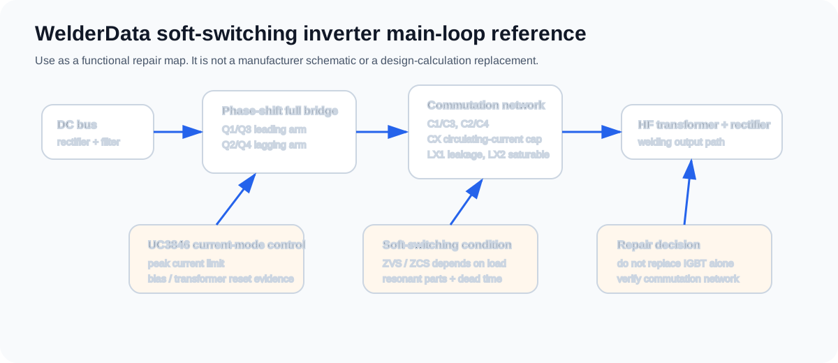
Main sections to separate
| Section | Repair interpretation | Why it matters |
|---|---|---|
| Phase-shift full bridge | Q1/Q3 are treated as the leading arm; Q2/Q4 are treated as the lagging arm. | The two arms do not fail under exactly the same commutation conditions. |
| Commutation capacitors | C1/C3 and C2/C4 shape switching transitions and reduce device stress. | A failed or changed capacitor can turn a soft-switching condition into hard switching. |
| CX circulating-current capacitor | Series capacitor used to limit or shape circulating current. | Wrong value, leakage or open condition changes light-load and no-load behavior. |
| LX1 leakage inductance | Transformer equivalent leakage inductance participates in commutation energy. | Transformer replacement, wiring layout or primary loop changes can change switching stress. |
| LX2 saturable inductor | Used to improve lagging-arm zero-current or transition behavior. | Heating, shorted turns or saturation drift can create repeated device failure. |
| UC3846 current-mode control | Peak-current control is used to protect switches and help prevent transformer bias. | A control failure can look like a power-stage fault if feedback and current limit are not separated. |
No-load and light-load repair warning
Soft switching is easiest to maintain when enough commutation energy is available. No-load and light-load operation can be the difficult region: reactive current may be insufficient, commutation may fail, and a bridge device may see a hard turn-on or hard turn-off condition.
For repair work, this means an inverter can destroy devices even when it is not welding at high current. If a repeated failure occurs during idle, arc-start or low-output testing, inspect resonant capacitors, saturable inductors, driver timing, dead-time behavior and transformer primary-loop evidence before installing another IGBT.
Repair checklist for repeated power-device failure
| Evidence | What to check | Do not conclude |
|---|---|---|
| Replacement IGBT fails immediately | Gate drive, resonant capacitors, leakage/saturable inductor and DC bus path. | Do not call it a bad new IGBT without commutation evidence. |
| Failure happens at no load or light load | CX, C1/C3, C2/C4, transformer primary loop and drive dead time. | Do not assume low current means low switching stress. |
| Turn-off spike or abnormal heating | Snubber/resonant parts, wiring loop, transformer leakage and feedback control. | Do not only increase device rating as a repair. |
| Bridge arms fail asymmetrically | Separate leading-arm and lagging-arm commutation conditions. | Do not compare all four devices as if the arm conditions are identical. |
No-load / light-load failure clues for repair
In an arc welder the load is not a fixed resistor. The same inverter may sit at open circuit, touch a near-shorted electrode, enter a low-current arc and then suddenly move to high welding current. A phase-shift soft-switching bridge can lose its intended commutation condition in the no-load or light-load region if the circulating or reactive current is not enough to discharge and recharge the bridge capacitances before the next device turns on.
For service work, this is a warning against judging the bridge only under one idle test. A machine may look safe with the output disconnected and still damage IGBTs when the arc-start condition, light-load condition or intermittent arc returns. Treat repeated device failure as a commutation-system problem until the resonant capacitors, leakage path, saturable inductor, drive timing and current-mode limit evidence are checked together.
Resonant-part repair meaning
| Part group | Repair meaning | Failure clue | Do not do this |
|---|---|---|---|
| C1 / C3 leading-arm capacitors | Shape the voltage transition of the PWM leading bridge arm. | Hard turn-off stress, asymmetric device heating or repeated failure on the same bridge side. | Do not replace with random capacitance or low pulse-current parts. |
| C2 / C4 lagging-arm capacitors | Assist lagging-arm commutation and zero-voltage / zero-current transition. | Bridge survives idle but fails during arc-start or light-load tests. | Do not assume these are ordinary snubber capacitors with no timing role. |
| CX circulating-current capacitor | Limits or shapes circulating current in the primary loop. | Excessive bridge current, abnormal primary heating or unstable current-mode limit behavior. | Do not short, omit or oversize it without confirming the topology. |
| LX1 transformer leakage path | Provides part of the commutation energy used by the bridge. | Fault appears after transformer, primary wiring or busbar service. | Do not reroute primary wiring casually on soft-switching machines. |
| LX2 saturable inductor | Helps the bridge transition under different load conditions. | Light-load failure, excessive heating, damaged insulation or changed magnetic behavior. | Do not bypass it because the welder appears to run at low power. |
UC3846 current-mode role in this topology
In this soft-switching reference, UC3846 is not only a generic PWM source. The design adapts current-mode control so the peak current limit can protect bridge devices and help prevent transformer bias. During repair, the technician should separate three types of evidence: whether the bridge receives drive, whether the current-sense path reaches the controller, and whether the current-mode limit is acting too early, too late or not at all.
A normal-looking PWM output does not prove the full soft-switching condition is healthy. If the current-sense path, timing network, dead-time condition or primary-loop resonant parts are wrong, the gate waveform may still exist while the power stage is operating outside its intended commutation window.
Related WelderData pages
Soft-switching commutation evidence before bridge restart
In a soft-switching or phase-shift full-bridge welder, the replacement bridge device can fail even when static gate pulses appear present. The commutation network decides whether the device turns on into a safe transition or into a destructive capacitor discharge.
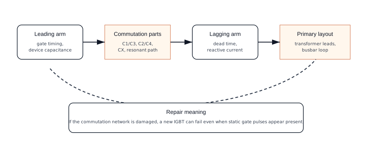
| Evidence group | What to check | Stop condition |
|---|---|---|
| Commutation capacitors | Paired capacitance, heat marks, cracks, substitution type, solder condition. | Any paired part is mismatched, unknown or heat damaged. |
| Leading / lagging arm behavior | Gate timing, dead time, branch temperature, failed-arm history. | One arm repeatedly fails while the other appears normal. |
| Primary loop / transformer path | Lead orientation, busbar layout, leakage inductance path, repaired wiring route. | Transformer or busbar service changed the original primary loop. |
| Current feedback | CT/shunt signal, current-mode input, protection timing, false current limit. | Bridge current limit is inconsistent with actual load evidence. |
Topology recognition before power-stage repair
Before replacing IGBTs, driver modules or control boards, identify whether the welder is single-ended, half-bridge, full-bridge or soft-switching. The number of gate branches, bus-balancing risk, transformer reset path and output rectifier stress change the safe diagnostic route.
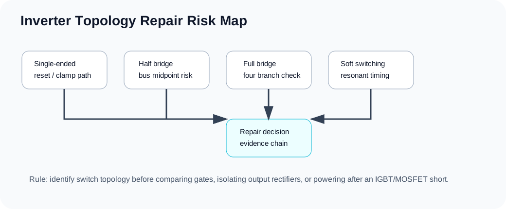
Soft-switching commutation evidence before bridge restart
In a soft-switching or phase-shift full-bridge welder, the replacement bridge device can fail even when static gate pulses appear present. The commutation network decides whether the device turns on into a safe transition or into a destructive capacitor discharge.
| Evidence group | What to check | Stop condition |
|---|---|---|
| Commutation capacitors | Paired capacitance, heat marks, cracks, substitution type, solder condition. | Any paired part is mismatched, unknown or heat damaged. |
| Leading / lagging arm behavior | Gate timing, dead time, branch temperature, failed-arm history. | One arm repeatedly fails while the other appears normal. |
| Primary loop / transformer path | Lead orientation, busbar layout, leakage inductance path, repaired wiring route. | Transformer or busbar service changed the original primary loop. |
| Current feedback | CT/shunt signal, current-mode input, protection timing, false current limit. | Bridge current limit is inconsistent with actual load evidence. |
Topology recognition before power-stage repair
Before replacing IGBTs, driver modules or control boards, identify whether the welder is single-ended, half-bridge, full-bridge or soft-switching. The number of gate branches, bus-balancing risk, transformer reset path and output rectifier stress change the safe diagnostic route.