Model family
Small Inverter Stick Welders
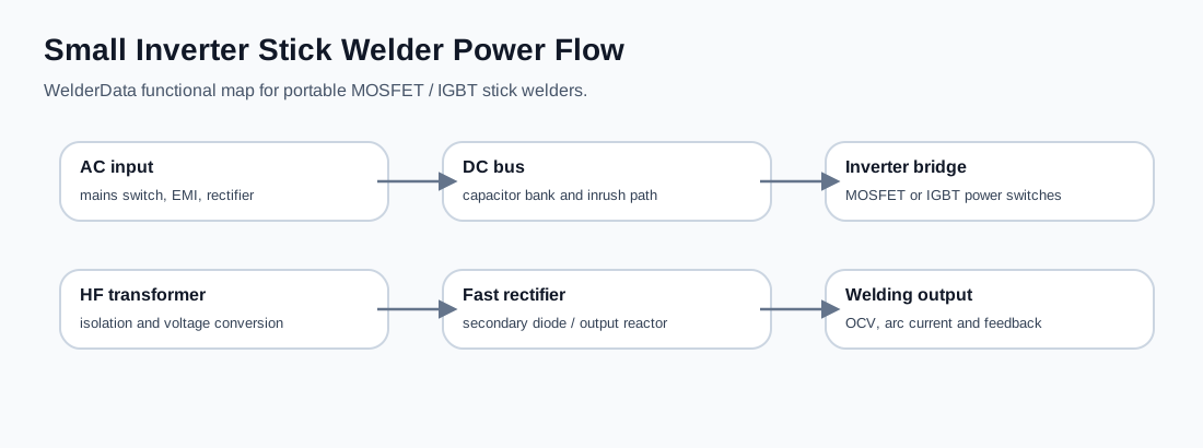
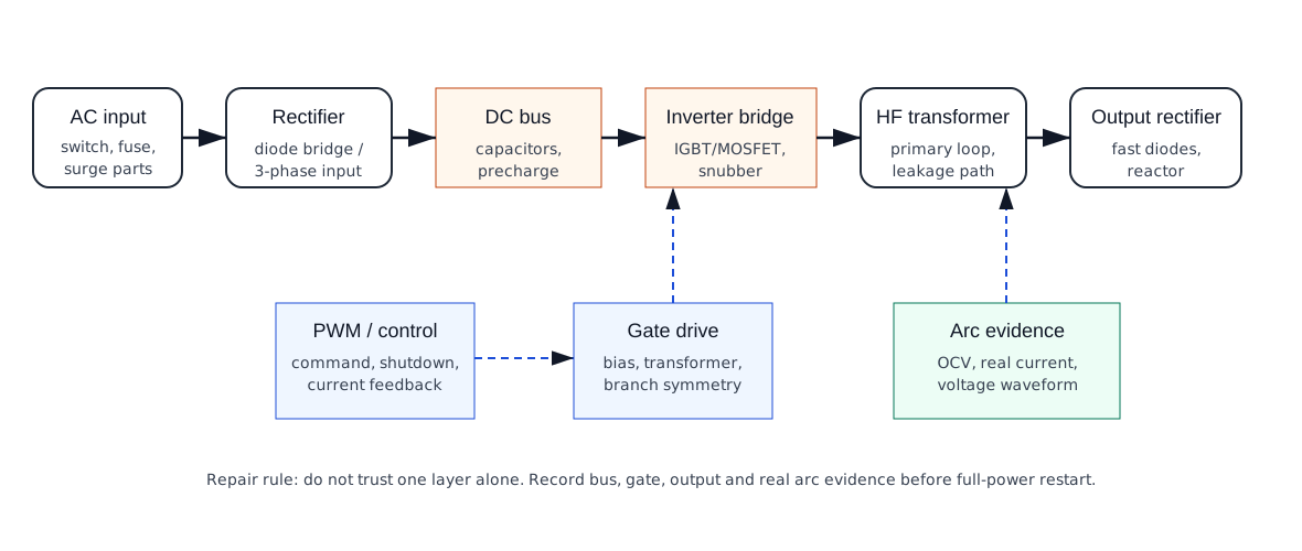
Portable stick welders are compact inverter power sources where the repair path usually begins with input rectification, DC bus safety, MOSFET or IGBT switching devices, high-frequency transformer drive, secondary rectification, feedback and protection behavior.
Database summary
WelderData groups small inverter stick welders as portable MOSFET or IGBT machines that share a common power-conversion structure: rectified mains, high-voltage DC bus, high-frequency switching bridge, transformer, secondary fast rectifier, output inductor and control board. The physical layout can be very different between brands, but the diagnostic order is similar.
This page is not a welding technique guide. It is a repair database hub for separating power-stage shorts, auxiliary supply loss, driver failure, output rectifier faults, fan/display-only symptoms and protection-lock behavior.
WelderData power-flow map
MOSFET versus IGBT field diagnosis
| Area | MOSFET portable inverter | IGBT portable inverter | Repair meaning |
|---|---|---|---|
| Power device failure | Drain-source short and gate damage are common after bus or driver stress. | Collector-emitter short and gate-emitter damage are common after overcurrent or weak drive. | Do not replace the device before checking driver bias, gate resistor, clamp path and snubber parts. |
| Driver behavior | Often discrete transformer or totem-pole drive in older compact machines. | May use transformer drive, opto-driver, hybrid driver or control-board push-pull stage. | Identify the drive family before applying ZX7-specific assumptions. |
| Secondary side | Fast recovery diodes or dual-diode modules can short and load the inverter. | Same output-rectifier risk, often with higher current modules. | Output diode-mode testing belongs before full-power restart. |
| Protection clues | Fan/display may work while PWM is disabled by protection. | Protection lamp or shutdown may be triggered by overcurrent, thermal or feedback abnormality. | Confirm low-voltage rails and protection inputs before judging the main PWM IC. |
Common repair sequence
- Record the symptom: no output, lamp-limiter bright, fan only, protection lamp, weak arc or repeated switch failure.
- Discharge and check the DC bus before resistance or diode-mode testing.
- Separate input rectifier, bus capacitor, switch bank, transformer primary and secondary rectifier paths.
- Verify auxiliary supply and driver bias before installing new MOSFETs or IGBTs.
- Use a staged power-up method: lamp limiter, bus confirmation, open-circuit voltage, then light-load weld test.
Soft-switching clue for compact inverter repair
Most compact inverter stick welders are diagnosed first through the input rectifier, DC bus, switch bank, gate drive and secondary rectifier. If the machine uses a soft-switching or resonant bridge, the technician must also check the commutation network. Replacing only MOSFETs or IGBTs without checking resonant capacitors, leakage-path parts, current-sense limit and dead-time behavior can produce another failure during the first restart.
Use the soft-switching reference only when the board layout or service evidence shows resonant capacitors, phase-shift bridge behavior, saturable inductors or a current-mode control path that is part of the main inverter loop.
Related WelderData pages
Soft-switching repair note
Portable inverter stick welders may use hard-switching, quasi-resonant or soft-switching bridge arrangements. When the platform uses a phase-shift or soft-switching design, resonant capacitors, saturable inductors, leakage inductance and dead-time conditions become part of the IGBT/MOSFET failure diagnosis. Do not treat every repeated power-device failure as a simple gate-driver or output-rectifier fault.
Topology repair risks in small inverter stick welders
Small inverter stick welders often look simple from the outside, but their repair risk depends on the internal topology. A single-ended forward machine, half-bridge machine and full-bridge machine can produce similar user symptoms while failing in different parts of the power loop.
| Topology / area | Repair risk | Evidence to collect |
|---|---|---|
| Single-ended forward | Switch and reset/clamp stress can be concentrated in fewer parts. | Check clamp/reset path, transformer primary and switch turn-off evidence. |
| Half bridge | Bus capacitor balance and arm symmetry become important. | Check bus capacitors, midpoint behavior, gate symmetry and transformer primary current. |
| Full bridge | One failed arm can hide a drive timing, snubber or transformer-loop problem. | Compare all four gate branches, snubber parts, output rectifier and current feedback. |
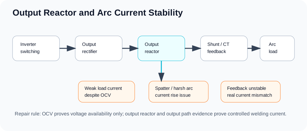
| Output reactor | Weak or unstable real current can appear even when OCV exists. | Record output rectifier, reactor, cable path, shunt/CT and load current evidence. |
Output reactor and loaded-current evidence
When a welder has open-circuit voltage but weak, harsh or unstable arc behavior, include the output reactor and output path in the evidence set. The reactor shapes current rise and decay, especially in CO2 / MIG short-circuit transfer, and can create process symptoms even when the control PCB appears normal.
Topology recognition before power-stage repair
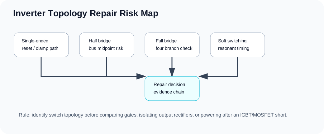
Before replacing IGBTs, driver modules or control boards, identify whether the welder is single-ended, half-bridge, full-bridge or soft-switching. The number of gate branches, bus-balancing risk, transformer reset path and output rectifier stress change the safe diagnostic route.
Topology repair risks in small inverter stick welders
Small inverter stick welders often look simple from the outside, but their repair risk depends on the internal topology. A single-ended forward machine, half-bridge machine and full-bridge machine can produce similar user symptoms while failing in different parts of the power loop.
| Topology / area | Repair risk | Evidence to collect |
|---|---|---|
| Single-ended forward | Switch and reset/clamp stress can be concentrated in fewer parts. | Check clamp/reset path, transformer primary and switch turn-off evidence. |
| Half bridge | Bus capacitor balance and arm symmetry become important. | Check bus capacitors, midpoint behavior, gate symmetry and transformer primary current. |
| Full bridge | One failed arm can hide a drive timing, snubber or transformer-loop problem. | Compare all four gate branches, snubber parts, output rectifier and current feedback. |
| Output reactor | Weak or unstable real current can appear even when OCV exists. | Record output rectifier, reactor, cable path, shunt/CT and load current evidence. |
Output reactor and loaded-current evidence
When a welder has open-circuit voltage but weak, harsh or unstable arc behavior, include the output reactor and output path in the evidence set. The reactor shapes current rise and decay, especially in CO2 / MIG short-circuit transfer, and can create process symptoms even when the control PCB appears normal.
Topology recognition before power-stage repair
Before replacing IGBTs, driver modules or control boards, identify whether the welder is single-ended, half-bridge, full-bridge or soft-switching. The number of gate branches, bus-balancing risk, transformer reset path and output rectifier stress change the safe diagnostic route.