Model
MZ1-1000 Submerged Arc Welder Control Reference
A WelderData model hub for MZ1-1000 submerged arc welder control logic, including travel-carriage thyristor speed control, wire-feed feedback, short-circuit retract arc start and 52V shutdown behavior.
Database summary
MZ1-1000 is treated in WelderData as an automatic submerged arc welder platform built around separate travel-carriage control, wire-feed control and arc-voltage feedback. It is not a compact inverter MMA welder like the ZX7 series. The repair logic is closer to motor control, relay sequencing, thyristor triggering and feedback stabilization.
The machine uses a welding tractor / carriage motor for travel, a wire-feed motor for electrode movement, a main welding power source and a control circuit that responds to arc voltage. The most important diagnostic idea is that the wire-feed motor is not only a speed-control load. Its direction and speed are part of the arc-starting and arc-voltage stabilization system.
Core control blocks
Travel carriage
W2 adjusts travel speed. G5, C10, G6, B4 and KP2 form a synchronized thyristor trigger path for the M2 carriage motor. Direction is selected by S7.
Wire-feed motor
The M1 wire-feed motor uses a related thyristor-control structure through D20-D23, W22, G3, G4, B3 and KP1, but it is controlled by the main arc-voltage feedback loop.
Arc-voltage feedback
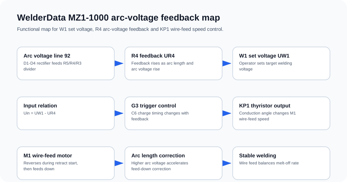
Arc voltage enters through line 92, is rectified by D1-D4 and divided through R5/R4/R3. The R4 feedback voltage is compared against the W1 set voltage.
Start / stop logic
AN1, AN2, AN5, relays J1-J4, contactor CJ and the 52V arc-voltage shutdown path determine how the machine starts, welds, stops and handles emergency stop.
MZ1-1000 control map
How this platform differs from ZX7 inverter repair
| Area | MZ1-1000 diagnostic focus | Repair implication |
|---|---|---|
| Travel | Carriage motor M2, KP2, W2 speed setting, S7 direction switch | Travel faults are motor-control faults, not welding-output faults only. |
| Wire feed | M1 motor, KP1, J4 direction relay and arc-voltage feedback | Wire-feed direction changes during short-circuit retract arc start. |
| Voltage control | W1 set voltage and R4 arc-voltage feedback | Welding voltage adjustment affects wire-feed behavior. |
| Current control | A1/A2 drive a regulating motor JD that changes transformer inductance | Welding current is adjusted through the main welding transformer mechanism. |
| Stop logic | 52V arc-voltage shutdown through WZ1 / J1 path | The machine can stop travel and feed first, then cut the main welding output after arc-voltage rise. |
W1 arc-voltage setting and A1 / A2 welding-current adjustment
MZ1-1000 adjustment logic differs from a small inverter welder. The welding-voltage setting is tied to the W1 arc-voltage setpoint and therefore changes the wire-feed feedback behavior. In practical terms, changing W1 changes how the machine balances wire feed against arc voltage during submerged arc welding.
Welding-current adjustment is handled through A1 / A2 commands to the regulating motor JD. One command drives JD in the direction that increases the main welding transformer’s inductance and output-current capability; the opposite command drives it back. CJ1 and CJ2 are interlocked so the motor is not commanded in both directions at the same time.
| Control | What it affects | Repair implication |
|---|---|---|
| W1 | Arc-voltage setpoint and wire-feed feedback behavior | Wrong W1 behavior can appear as wire-feed or arc-length instability. |
| A1 / A2 | Regulating motor JD direction | Check interlock and motor direction before blaming transformer output. |
| CJ1 / CJ2 | Forward / reverse motor-control interlock | Do not allow both directions to energize together. |
| JD | Main transformer inductance adjustment | Mechanical or motor fault can appear as current-control failure. |
MZ-1000 maintenance and fault examples
For broader AC/DC MZ-1000 submerged arc maintenance checks, wire-sticking evidence and power-source / tractor separation, use the MZ-1000 AC/DC maintenance and fault examples workflow.
Related WelderData records
Model-family context
MZ1-1000 is one member of a wider submerged arc family that also includes MZ, MZ2, MU, MZD and MZN variants. When the machine under repair is not clearly an MZ1-1000 single-wire platform, compare the symptom against the broader model-family index before applying MZ1-specific wire-feed or 52V shutdown conclusions.