Circuit
MZ1-1000 Arc-Voltage Feedback and Wire-Feed Control Logic
A WelderData circuit reference for the arc-voltage negative-feedback loop that controls MZ1-1000 wire-feed motor speed and direction during submerged arc welding.
Database summary
This WelderData circuit record describes the MZ1-1000 arc-voltage feedback loop used to control the wire-feed motor. The machine does not treat wire feed as a simple manual motor speed setting during welding. Arc voltage is sampled, rectified and compared with a voltage setpoint so the wire-feed motor can speed up, slow down, stop or reverse during the arc-starting and stabilizing process.
The useful repair equation is the control relationship Uin = UW1 - UR4. UW1 is the set voltage from the welding-voltage potentiometer W1. UR4 is the feedback voltage developed across R4 in the arc-voltage divider. When the arc length changes, arc voltage changes, UR4 changes and the G3 / C6 / G4 / KP1 wire-feed control path changes the M1 motor behavior.
WelderData feedback map
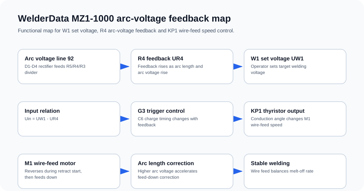
Signal path
- Arc voltage is introduced through control line 92.
- D1-D4 rectify the sampled arc voltage into the feedback path.
- R5, R4 and R3 form the divider; R4 provides the feedback voltage UR4.
- W1 provides the welding-voltage setpoint UW1.
- The control input is the difference between setpoint and feedback: Uin = UW1 - UR4.
- G3 current controls C6 charge timing and therefore the trigger timing of the unijunction / thyristor path.
- KP1 changes the DC voltage applied to the M1 wire-feed motor.
Feedback behavior during welding
| Observed arc condition | Control response | Repair meaning |
|---|---|---|
| Arc voltage rises because the arc length increases | UR4 rises and the feedback loop increases wire-feed correction | The machine attempts to feed wire down faster and reduce arc voltage. |
| UR4 equals UW1 | Uin approaches zero and the motor may stop momentarily | This is a balance point in the feedback loop, not necessarily a motor fault. |
| Arc voltage falls | The direction of control correction reverses | Check whether the feedback divider, D1-D4 and J4 reversal logic are functioning. |
| No feedback action | Wire speed no longer follows arc voltage | Check line 92, D1-D4, R5/R4/R3, W1, G3 input and KP1 trigger path. |
Repair checks
- Confirm the arc-voltage feedback line is connected and not open.
- Check D1-D4 for open or shorted rectifier behavior.
- Measure the R5/R4/R3 divider network and confirm R4 feedback is not missing.
- Check W1 setpoint continuity because it defines the target welding voltage.
- Inspect G3 bias and C6 charge timing if KP1 trigger angle does not change.
- Check R13 and R14 if maximum wire speed or starting wire-feed behavior is incorrect.
- Inspect D11 if the G3 bias path does not switch correctly around the J4 relay reversal interval.
R13 / R14 wire-feed calibration and D11 bias switching
The wire-feed control section includes calibration points that should not be treated as ordinary fixed resistors. R13 is used as a maximum wire-feed speed correction point, while R14 is used as a starting-speed correction point. These two adjustments help the M1 wire-feed motor respond correctly during initial wire positioning, retract arc start and stable welding.
D11 works as a bias-switch element for the G3 input path. When the DC side of D12-D15 is above the approximate diode-conduction level, D11 conducts and enables the G3 bias path. When that voltage falls below the conduction level, the bias path is cut off. This helps the J4 direction-change contacts transfer with reduced current, lowering the risk of contact burning during reversal.
| Part | WelderData role | Repair note |
|---|---|---|
| R13 | Maximum wire-feed speed correction | Use only after the motor and thyristor trigger path are confirmed. |
| R14 | Starting-speed correction | Incorrect adjustment can affect short-circuit retract arc start. |
| D11 | G3 bias switching | Check if J4 reversal timing or contact stress is abnormal. |
| D12-D15 | DC bias supply for the switching path | Low DC side voltage can disable the G3 bias path. |