Circuit
MZ1-1000 Travel Carriage Thyristor Speed Control Circuit
A WelderData circuit reference for MZ1-1000 travel carriage speed control, including synchronized triggering, unijunction pulse generation, KP2 thyristor output and M2 DC motor behavior.
Database summary
This circuit record explains the MZ1-1000 travel carriage speed-control path. The carriage motor M2 is controlled through a synchronized thyristor trigger system. W2 changes the timing of a charge-and-trigger network so KP2 receives an earlier or later gate pulse, changing the conduction angle and therefore the DC armature voltage applied to M2.
This page is useful for faults such as travel carriage not moving, travel speed not adjustable, carriage running away after board repair, direction not changing or unstable motion under load.
WelderData travel-control map
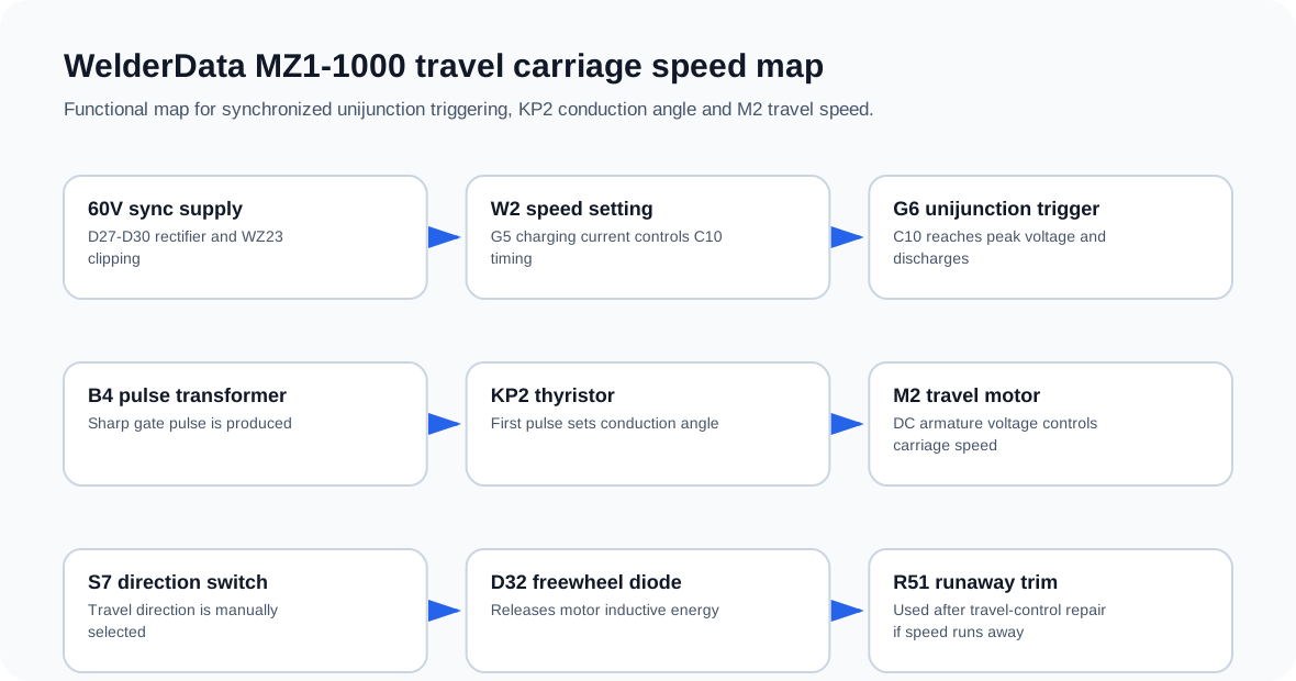
Control sequence
- The synchronous secondary voltage is rectified through D27-D30 and clipped by WZ23 to produce a synchronized trapezoid-style control reference.
- W2 changes the bias and charging current through G5, controlling how quickly C10 charges.
- When C10 reaches the G6 unijunction peak voltage, G6 turns on and discharges through the pulse-transformer primary path.
- B4 provides a sharp trigger pulse for the KP2 thyristor gate path.
- The first trigger pulse in the synchronized period determines KP2 conduction timing.
- Earlier triggering increases average motor voltage; later triggering reduces M2 travel speed.
Field repair interpretation
| Symptom | Likely area | Next check |
|---|---|---|
| No carriage movement | M2 field / armature supply, KP2 trigger, S7 direction path | Check motor field supply, KP2 gate pulse and direction switch continuity. |
| Speed cannot be adjusted | W2, G5, C10, G6 or B4 trigger chain | Confirm C10 charge behavior and G6 pulse generation. |
| Carriage runs away after repair | Positive feedback / speed trim path | Inspect R50-R52/C21 network and adjust R51 according to repair condition. |
| Motor stops with high inductive kick behavior | Freewheel path | Check D32 and the motor armature suppression path. |
| Direction cannot change | S7 direction switch and wiring | Check switch poles, motor leads and mechanical travel wiring. |
Important control note
KP2 and its trigger circuit require a synchronized pulsating supply with zero-crossing behavior. If the supply is incorrectly filtered or no longer synchronized, a thyristor stage may lose its ability to turn off and regulate. This is a key difference between this carriage speed-control circuit and a simple DC motor power supply.
Runaway carriage speed and R51 correction
The MZ1-1000 travel carriage circuit includes an armature-current positive-feedback path around R50, R51, R52 and C21. Its purpose is to improve the carriage motor’s load response, but after replacing speed-control parts the feedback trim may no longer match the repaired circuit.
If the carriage accelerates unexpectedly, cannot settle at the W2 speed setting or behaves like a runaway motor after repair, do not only suspect the M2 motor. Inspect the positive-feedback network and adjust R51 carefully while confirming the thyristor trigger chain remains synchronized. A runaway condition is a service stop condition; the machine should not be allowed to enter welding travel until speed response is stable.
| Condition | Interpretation | Next action |
|---|---|---|
| Carriage speed too high after control-part replacement | Feedback trim may be excessive or mismatched. | Inspect R50-R52 / C21 and correct R51 setting. |
| W2 changes little but motor runs hard | Trigger timing or feedback path may dominate speed control. | Check C10 / G6 trigger timing and R51 feedback network. |
| Speed unstable under load | Feedback compensation or motor armature path may be abnormal. | Check M2, KP2 output, freewheel path and feedback components. |
Related pages
MZC travel and weld-quality setup checks
Travel-speed faults should not be diagnosed only at the SCR speed-control section. The MZC setup state also matters: travel speed, direction, debug/weld mode, start mode and cable length compensation can all change the symptom.
| Symptom | Check before component replacement | Interpretation |
|---|---|---|
| Travel carriage does not move | Mode switch, direction command, motor connection and controller output | Do not judge KP2 or the trigger circuit until command evidence exists. |
| Travel carriage runs away | Speed feedback / armature-current positive-feedback path and R51 adjustment | Runaway after component replacement may need correction, not another motor. |
| Weld bead is unstable while travel appears normal | Travel speed, arc-voltage setting, wire-feed mode and output cable | Separate travel setup from ZD5 power-source output faults. |
| Wire sticks at weld end | Burn-back time, crater settings and arc voltage | The stop sequence is a separate diagnostic branch from start sequence. |