Diagnostic workflow
Panasonic KR P-Board D1-D5 Fuse Fault
P-board fault reference for FU2 / FU3 fuse placement, +24V short damage, D1-D5 rectifier diodes, Q10 brake transistor and control-cable short evidence.
Database summary
This page records a high-value Panasonic KR P-board fault pattern: D1-D5 rectifier diode damage around the FU2 / FU3 fuse area, plus related Q10, IC5 and R245 damage when the feeder cable or torch-control wiring is shorted or wet.
The important repair rule is simple: do not replace the P-board or oversize fuses until the cause of the 24V short, feeder overload or control-cable short has been found.
P-board fuse and short map
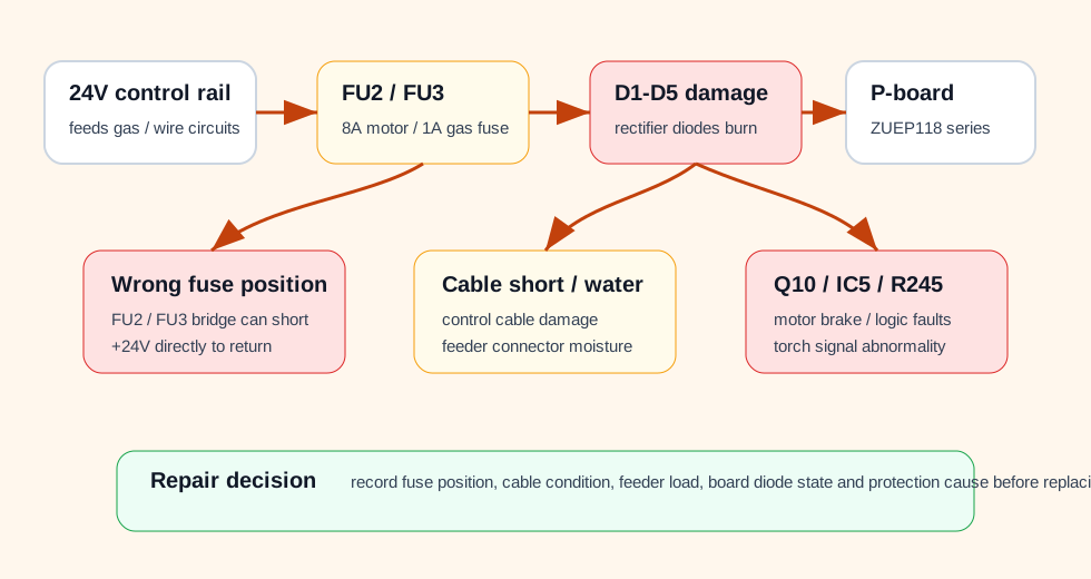
WelderData functional map for KR P-board fuse-position, +24V short, D1-D5 diode damage and Q10 / IC5 / R245 related faults.
FU2 / FU3 and D1-D5 failure logic
| Item | Reference | Repair meaning |
|---|---|---|
| FU2 | 8A wire-feed motor fuse area | If it blows immediately, inspect feeder load, wire-feed circuit, Q10 path and motor drive before installing another fuse. |
| FU3 | 1A gas-valve fuse area | If replaced by an oversized 8A or 10A fuse, the protection role is lost and P-board rectifier diodes may be damaged during a short. |
| Wrong fuse placement | Fuse accidentally placed between FU2 / FU3 socket positions | Can short the +24V supply path to return and burn D1-D5. |
| D1-D5 | P-board rectifier diode group | Damage may appear as one diode or multiple diodes open/shorted; the cause must be recorded before diode replacement. |
| Control cable short | Feeder cable insulation damage or water ingress | Can create abnormal logic states or direct short paths that repeatedly damage board parts. |
Q10 wire-feed brake transistor failure
Some KR P-board faults appear as the FU2 8A wire-feed fuse blowing immediately when the torch switch is pressed. A known routing point is the Q10 brake transistor path. Q10 can be damaged when extended feeder connectors get wet or when control cable conductors short together.
| Evidence | Check | Decision |
|---|---|---|
| FU2 8A blows when torch is pressed | Measure Q10 drain-source and gate-source resistance, then inspect feeder SCRs and feeder motor circuit. | If Q10 is shorted, also inspect cable and motor load; otherwise the replacement board may fail again. |
| Extended control cable exposed to water | Open connectors, dry and inspect pins, measure conductor-to-conductor insulation. | Moisture faults should be resolved before board replacement. |
| Control cable line short | Check feeder cable continuity and shorts between control lines. | Record cable condition as root-cause evidence. |
IC5 / R245 abnormal start fault
The KR P-board information also identifies IC5 and R245 damage patterns. IC5 damage may cause no-load voltage and wire feed to appear immediately after the power switch is turned on. R245 damage can appear in torch-switch related abnormal operation. These faults are strongly linked to control-cable shorts and output-cable-to-control-cable contact.
| Failure pattern | Typical cause to investigate | Repair note |
|---|---|---|
| IC5 damage | Control cable conductor shorts such as 47/67/61 combinations, or frequent torch switching while shorted. | Inspect cable and torch-switch wiring before replacing logic ICs. |
| R245 damage | Long-duration 47/61 short or output cable contacting control cable conductors. | Separate welding output cables from control cables and repair insulation first. |
| Immediate no-load voltage and feed | Logic path stuck as if torch command is present. | Do not treat it as a normal feeder motor fault; route through P-board command logic and cable shorts. |
Post-fuse-fault inspection sequence
After a FU2 / FU3 fuse event, D1-D5 diode damage or Q10 / IC5 / R245 failure, the repair should be routed as a cause-finding sequence. Replacing the board first can hide the fault that damaged it.
| Sequence | Check | Reason |
|---|---|---|
| 1 | Confirm the correct fuse rating and physical fuse position. | FU2 / FU3 misplacement or oversized fuses can convert a protected branch fault into P-board damage. |
| 2 | Inspect feeder cable insulation, water ingress and conductor-to-conductor shorts. | Control cable shorts are a repeated root cause of diode, transistor and logic-path damage. |
| 3 | Measure D1-D5 with diode mode out of circuit when readings are unclear. | One damaged rectifier diode can load the control supply and produce misleading symptoms. |
| 4 | Check Q10 and feeder brake / motor-control path. | Immediate 8A fuse failure with torch command may point to brake transistor or motor-drive short evidence. |
| 5 | Check IC5 / R245 and stuck torch-command evidence. | Unexpected feed or no-load voltage at power-on can be a command-logic fault, not a motor fault. |
| 6 | Reconnect with a verified cable and correct fuses before final functional testing. | Functional testing with the same shorted cable can damage the repaired board again. |
Do not oversize the protection fuse
If a 1A protection position is replaced with an 8A or 10A fuse, the fuse may no longer open before P-board rectifiers, transistors or traces are damaged. Treat any oversize-fuse history as root-cause evidence, not as a successful repair.