Circuit
MIG / MAG Wire-Feed and Voltage Control Logic
A WelderData circuit reference for separating wire-feed speed control, welding-voltage control, gas valve command, trigger input and crater-fill behavior in CO2/MIG/MAG welders.
Database summary
In a conventional CO2/MIG/MAG welder, the welding power source and the wire feeder work as a coupled system. The voltage setting controls arc voltage at the power source. The wire-feed speed sets the rate of electrode delivery and strongly affects the welding-current trend. A fault in either path can look like poor arc quality, unstable current, wire stubbing, burn-back or no output.
For repair diagnosis, the important separation is between command, motor drive, gas valve and welding output. A working feeder motor does not prove voltage output is healthy, and a working gas solenoid does not prove the wire-feed control path is intact.
WelderData control map
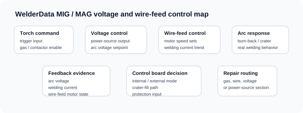
Wire-feed speed as current-control evidence
In many constant-voltage CO2/MIG systems, current is not adjusted in the same way as a stick inverter current knob. Increasing wire-feed speed pushes more electrode into the arc and causes the welding current to rise. If a machine shows maximum current, weak current or unstable current, record the actual feeder behavior before replacing the power board.
Useful checks include motor supply, motor driver device, speed potentiometer, remote/internal selector, feeder harness and jog circuit. If the jog function works but torch-trigger feed does not, the trigger/logic path is more likely than the motor itself.
Voltage control and arc behavior
The voltage setting changes the welding power-source output and therefore the arc length behavior. A machine with normal wire feed but no stable arc may have a voltage-control, contactor, rectifier, SCR/inverter output or feedback issue. If voltage is stuck at maximum, inspect the command line and feedback amplifier before assuming a main transformer or rectifier fault.
Crater-fill, burn-back and stop timing
Some CO2/MIG machines include crater-fill, burn-back or stop-delay timing. At the end of welding, the machine may reduce the command, keep output active briefly, stop the motor after a delay or continue gas flow for a controlled finish. A wrong stop sequence can leave wire stuck in the weld pool, burn the wire back into the contact tip, or make the machine stop with an unstable crater.
For diagnosis, separate three commands: feeder motor stop, welding-voltage stop and gas post-flow. If wire sticks at the end, check burn-back and motor stop timing. If the contact tip is repeatedly damaged by burn-back, check whether output remains active after wire feed has stopped. If gas timing is wrong but arc and feed are normal, route the fault to gas solenoid timing rather than the power source.
Remote / local and feeder-interface checks
When panel controls appear ineffective, verify whether the machine is operating from internal controls, external feeder controls or a remote interface. A broken command line can make voltage or wire-feed speed stay at maximum, minimum or a fixed value even when the power stage is healthy. Use the feeder harness and the 6-wire fault table as first evidence before replacing the main control board.
Related pages
When the machine is a pulse MIG/MAG platform
If the base feeder, gas and voltage functions are correct but the pulse action is missing or fixed, move from ordinary MIG routing to pulse waveform diagnosis. Peak current, base current, frequency and duty commands should be checked before blaming the output stage.
Related repair map
Follow the evidence path from symptom to measurement, circuit and repair case.