Diagnostic workflow
Welding Machine EMI and Noise Interference Routing
Use this WelderData workflow when welding operation interferes with nearby electronics, control cables, remote interfaces or signal lines. It separates cable layout, grounding, output-current loop area and filter checks before blaming a control PCB.
Database summary
Inverter welders, CO2/MIG machines, TIG HF-start systems and high-current power sources can create conducted and radiated noise. The first repair task is to decide whether the symptom is a machine fault, a wiring-layout problem, a grounding problem or an external-equipment susceptibility problem.
For Panasonic RF2-style inverter CO2 machines and other modern inverter welders, WelderData treats EMI evidence as part of the service record: where the welding cable runs, how the work return is routed, whether signal wires are long and unshielded, and whether external equipment shares the same power or ground path.
EMI routing map
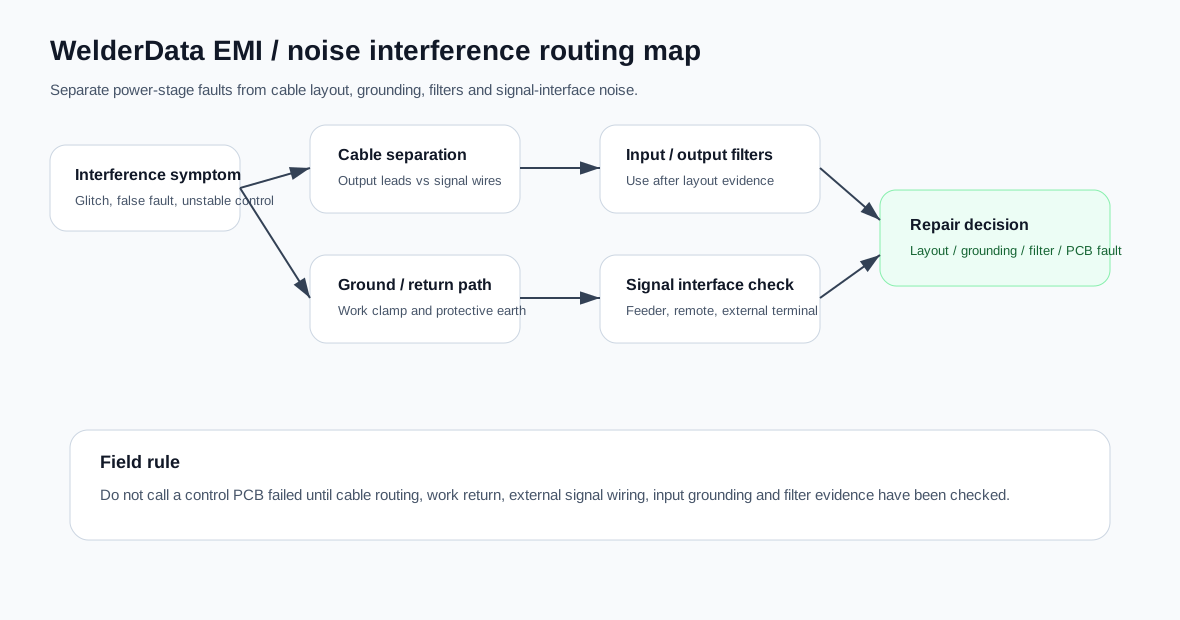
WelderData functional map for cable separation, grounding, output loop, filter and signal-interface checks.
Symptom-to-check routing
| Observed symptom | First evidence to collect | Likely next check |
|---|---|---|
| Nearby electronics glitch only while welding | Distance between welding cables and electronic-device wiring. | Separate cable routes and reduce the loop area of the welding current path. |
| Remote-control or feeder signal becomes unstable | Length, shielding and routing of external signal conductors. | Keep control leads away from output cables; inspect connector shield and ground reference. |
| Interference changes with cable layout | Whether torch/output and work-return cables are long, parallel to other cables or coiled. | Shorten output cables, route return close to output path and avoid unnecessary coils. |
| Noise enters through AC input | Whether the welder and sensitive device share input supply, extension cable or distribution board. | Use proper input grounding and consider an input noise filter where appropriate. |
| False fault state or erratic display | Whether the symptom appears only during arc ignition or high-current welding. | Check grounding, signal wire routing, PCB connectors and external terminal wiring before replacing the PCB. |
Cable, grounding and filter checklist
- Separate welding cables from signal cables. Do not run output leads beside torch-control, feeder, remote, sensor or communication cables.
- Keep welding-current cables short and paired where possible. A large output-current loop radiates more noise.
- Check work-return contact. A poor work clamp increases arc instability and noise.
- Use a dedicated protective ground according to the machine manual. Do not invent unsafe ground paths through signal wiring.
- Inspect external output-signal terminals. Long unshielded external wires can inject noise back into the control board.
- Use filters as the last step, not the first guess. Input or equipment-side noise filters can help, but only after wiring layout and grounding are correct.
Stop conditions
Stop troubleshooting and make the machine safe if interference is accompanied by smoke, abnormal inverter noise, repeated overcurrent alarms, erratic contactor action, overheated cables, damaged insulation or unstable output current. EMI routing should not be used to hide a real power-stage fault.