Diagnostic workflow
ZX7-250 Staged Power-Up Checklist After IGBT or Driver Repair
A WelderData post-repair validation workflow for reassembling a ZX7-250, restoring the DC bus in stages, confirming no-load output and verifying real welding current with an external meter or shunt.
Database summary
This WelderData diagnostic record covers the final validation stage after a ZX7-250 power-device or driver repair. The purpose is not to prove that one replacement part was installed. The purpose is to prevent the repaired machine from being returned directly to full-load operation before the control board, high-voltage bus, no-load output and real-current evidence have been checked.
The validation sequence recorded here follows a conservative repair path: restore the missing or damaged small parts, reinstall the output board and signal board, mount the replacement power devices with fresh thermal compound, keep the 500V-class DC bus path disconnected for the first low-risk start when possible, then reconnect and measure the bus, output voltage and real welding current.
WelderData staged power-up map
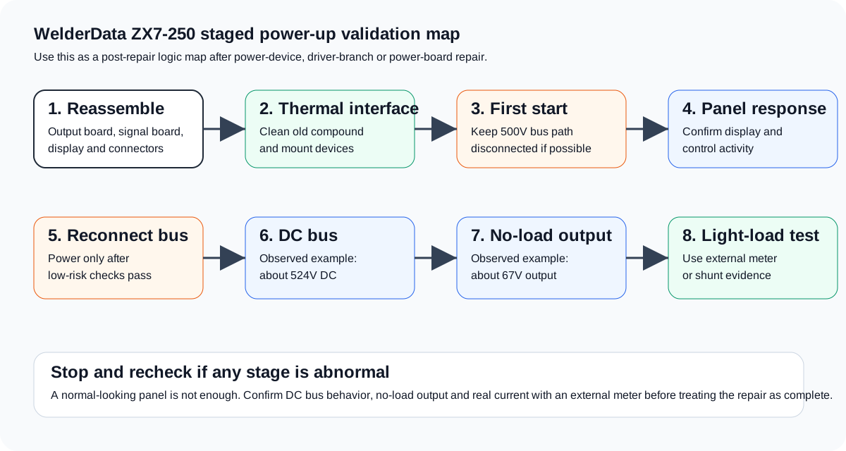
Staged validation checklist
| Stage | What to confirm | Why it matters |
|---|---|---|
| Board reassembly | Output board, signal board, display panel and connectors are restored in the correct locations. | A missing connector or mis-seated board can create a new no-output symptom unrelated to the repaired fault. |
| Thermal mounting | Old compound is removed and fresh thermal compound is applied before mounting IGBT, MOSFET or H7B-style devices. | A good electrical repair can fail thermally if the device is mounted dry or unevenly. |
| Low-risk first start | The machine is powered with the high-voltage DC bus path kept disconnected where the board layout permits. | This confirms display and control activity before the main bus is allowed to stress the power stage. |
| DC bus measurement | After reconnecting the bus path, measure the high-voltage bus. This repair pattern recorded about 524V DC. | Bus voltage proves that the rectifier, relay/boost path and bus capacitors are producing energy for the inverter stage. |
| No-load output | Measure output terminal voltage before welding. This repair pattern recorded about 67V open-circuit output. | No-load output is a major confirmation that the inverter is switching and the secondary output path is active. |
| Real-current test | Use an external current meter or shunt during a controlled light-load welding test. This repair pattern recorded about 50A during the test. | Panel display alone is not proof of real output current. External current evidence closes the repair loop. |
Stop-and-recheck conditions
- The display is normal but the DC bus does not rise to a credible value.
- The DC bus is present but there is no no-load output voltage.
- No-load output exists but an external current meter or shunt shows no real welding current.
- The lamp limiter stays bright after the repaired power stage is reconnected.
- The output voltage collapses immediately under a light test load.
- Any repaired branch heats abnormally during the first controlled test.
How this differs from a normal power-on
A repaired inverter should not be treated like a healthy machine on its first restart. The first restart is still a diagnostic event. The panel may light, the fan may run and the display may respond while the high-voltage section remains unproven. WelderData therefore separates control-side response, DC bus restoration, output voltage and real-current evidence into different checkpoints.
The observed values in this ZX7-250 repair pattern are service evidence, not universal nameplate values. A bus reading around 524V and an open-circuit output around 67V are useful reference points for this repair path, but technicians should compare readings with the actual input configuration, board version and safety condition of the machine under test.