Diagnostic workflow
ZX7-315 / 400 / 500 / 630 PCB Test Points and Calibration Workflow
Use this workflow when a large ZX7 IGBT inverter welder needs board-level voltage references, current adjustment evidence or fault routing before PCB replacement.
Database summary
This WelderData workflow converts the ZX7-315 / ZX7-400 / ZX7-500 / ZX7-630 PCB service table into a practical repair sequence. It is intended for qualified technicians checking PCB1-style control boards after symptoms such as undervoltage indication, overcurrent indication, current not adjustable, weak output, no no-load voltage or panel-display mismatch.
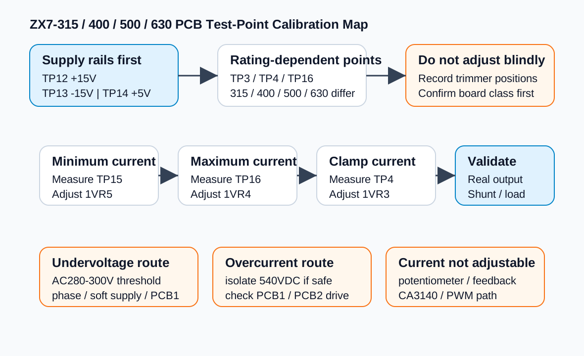
The key value is measurement separation. TP12, TP13 and TP14 prove the basic +15V, -15V and +5V rails. TP15, TP16 and TP4 support current calibration. TP3, TP4 and TP16 are rating-dependent, so a 315A board and a 630A board should not be forced to the same values.
ZX7 PCB test-point and calibration map
TP1-TP16 voltage reference table
| Test point | Reference | Repair interpretation |
|---|---|---|
| TP1 | -3.63V | Low-voltage control reference. If abnormal, confirm board reference ground and supply integrity first. |
| TP2 | 2.5V | Internal control-loop reference; useful when setpoint or feedback behavior is inconsistent. |
| TP3 | 315: -0.2 to -3.2V; 400: -0.2 to -4V; 500: -0.2 to -5V; 630: -0.2 to -6.3V | Rating-dependent command/control range. Do not compare different current classes as if they were the same board setting. |
| TP4 | 315/400: 4.05V; 500: 5V; 630: 6.3V | Maximum clamp-current adjustment evidence; adjusted with 1VR3 in the service procedure. |
| TP5 | 0.015V | Low-level reference/feedback evidence; verify meter resolution and reference point. |
| TP6 | 3V | Control-board signal reference used to separate board reference faults from power-stage faults. |
| TP7 | Waveform / signal point | Use oscilloscope only with safe isolation practice and a known reference point. |
| TP8 | 1.1V | Control signal reference. |
| TP9 | 2.89V | Control signal reference. |
| TP10 | Long: 2.18V; short: 1.69V | Output-cable length mode evidence; wrong mode can be mistaken for harsh arc or abnormal control behavior. |
| TP11 | Long: 2.08V; short: 1.48V | Second cable-mode evidence point. |
| TP12 | +15V | Positive analog/control supply rail. Check this before feedback calibration. |
| TP13 | -15V | Negative analog/control supply rail. Missing -15V can break current feedback and comparator behavior. |
| TP14 | +5V | Logic/control rail. Missing +5V can make panel and protection behavior unreliable. |
| TP15 | -0.4V | Minimum-current calibration evidence; adjusted with 1VR5. |
| TP16 | 315: -6.3V; 400: -8V; 500: -10V; 630: -12.6V | Maximum-current calibration evidence; adjusted with 1VR4. |
Calibration sequence
| Step | Measure | Adjust | What to record |
|---|---|---|---|
| Confirm board current-class jumper | Jumper / shorting plug for 315, 400, 500 or 630 class | Do not adjust yet | Machine rating, board revision and jumper state. |
| Minimum current | TP15 | 1VR5 | Voltage before adjustment, after adjustment and current knob position. |
| Maximum current | TP16 | 1VR4 | Expected value for the machine rating and the final measured value. |
| Maximum clamp current | TP4 | 1VR3 | Expected clamp value and whether protection behavior is normal after adjustment. |
| Final validation | Real output evidence | No random trimming | External current/shunt evidence, no-load voltage and staged output test result. |
Use this page for these symptoms
Current cannot be adjusted
Use TP15, TP16 and TP4 after verifying the panel potentiometer and PCB1 current-feedback / given-current circuit. Do not recalibrate before the command path is known to be alive.
Undervoltage lamp on
Use the test points only after input voltage, phase presence and soft input supply behavior have been checked. The undervoltage threshold is around AC280V-300V in this service family.
Overcurrent lamp on
Do not keep full-power restarting. The service path calls for isolating the high-voltage 540VDC path where safe and checking PCB1 / PCB2 drive evidence before reconnecting the main bus.
Display does not match output
Separate the front-panel display, command voltage, feedback voltage and real output current. A display number is not the same evidence as welding current.
Stop conditions
- Stop if TP12, TP13 or TP14 rails are missing or unstable; repair supply rails before calibration.
- Stop if the machine has active overcurrent protection and power modules have not been checked offline.
- Stop if the board reference point is unclear; wrong meter reference can create false readings.
- Stop if trimmer positions were not recorded before adjustment.
- Stop if the machine rating and current-class jumper do not match the calibration values being used.