Fault diagnosis
ZX7 Welder Current Cannot Be Adjusted: Potentiometer, Feedback and PCB1 Checks
Diagnosis for ZX7 inverter welders where the current knob does not respond correctly, separating potentiometer faults from PCB1 current-feedback and command-circuit faults.
Symptom definition
“Current cannot be adjusted” means the front panel welding-current knob no longer changes the output command or the displayed current reference in the expected way. On this ZX7 series the manual points to two primary branches: the regulating potentiometer itself or the PCB1 current feedback and given-current circuit. This is a narrower symptom than “no output”. The machine may power on, the fan may run and the protection indicators may remain normal, while the current command remains fixed, erratic or unresponsive.
Do not start with the power modules
For this symptom, the first suspect is not the IGBT module. The IGBT stage follows the PWM command generated by the control board. If the command path is wrong, the output may be low, high, unstable or absent even though the power devices are not shorted. Start from the human interface and low-voltage feedback loop, then move toward the PWM section.
| Check | Expected service meaning | Action |
|---|---|---|
| RP1 welding-current potentiometer | Resistance should vary smoothly without dead zones. | Replace the potentiometer or repair wiring if the signal jumps or remains open. |
| Panel harness | The given-current signal must reach PCB1. | Inspect connector pins, cracked solder and broken conductors. |
| PCB1 current feedback/given section | Feedback and command meet around the control amplifier stage. | Inspect CA3140 area, feedback input and command conditioning network. |
| PWM response | Changing current command should affect the PWM control path. | If the command changes but PWM does not, continue to the PWM/control board branch. |
PCB1 current feedback and given-current logic
The reference circuit shows a CA3140 operational amplifier section with current feedback, current setting input and a path toward pulse-width modulation. This is important because the knob is only one part of a closed-loop system. The board compares the selected current command against sensed current feedback. A fault in either side can make the front control appear ineffective.
When diagnosing, separate the problem into three questions. First, does the potentiometer create a changing command voltage? Second, does PCB1 receive and condition that command? Third, does the PWM system respond to the conditioned control signal? If the answer fails at the first step, repair the panel control. If the answer fails at the second or third step, repair PCB1 rather than replacing front-panel parts again.
Recommended repair procedure
- Power off the welder, discharge stored energy and inspect the current knob mechanically.
- Measure the potentiometer through its range. A smooth change indicates the component may be serviceable.
- Inspect the panel connector, solder joints and cable between RP1 and PCB1.
- Check the PCB1 current command and current feedback area, especially around the CA3140 section.
- After repair, verify minimum current, maximum current and clamp-current adjustment against the PCB test-point reference.
Typical user complaints
Technicians may hear this fault described as “the knob does nothing,” “the machine stays at maximum,” “the current display changes but the arc does not,” or “the current jumps suddenly.” These are not identical. If the display value does not change, the problem may be the panel control or command input. If the display changes but output does not, the feedback loop, PWM command or output sensing path may be involved.
Separate the displayed set value from the real welding current. A front-panel display can follow the knob even when the actual output remains wrong. The repair should verify both the command side and the feedback side.
After replacing the potentiometer
If RP1 is replaced, calibration should not be skipped. The board still needs correct minimum, maximum and clamp-current adjustment. Use the PCB test-point page to confirm TP15, TP16 and TP4 according to the welder current rating. A new potentiometer with the wrong value, wrong wiring order or poor connector contact can create a different current-control fault.
ZX7-315 / 400 / 500 / 630 TP-based current adjustment checks
When the current knob does not respond, use the TP workflow after confirming the potentiometer and harness. Minimum current is checked at TP15 and adjusted with 1VR5. Maximum current is checked at TP16 and adjusted with 1VR4. Maximum clamp current is checked at TP4 and adjusted with 1VR3.
| Complaint | Check | Interpretation |
|---|---|---|
| Current stays too low | TP16 maximum-current reference for the model class | If command path works but TP16 cannot align, the PCB1 feedback/control section is suspect. |
| Current cannot reduce | TP15 minimum-current reference | Wrong minimum-current calibration or command-path fault may hold output too high. |
| Protection or harsh current behavior | TP4 clamp-current reference | Do not adjust clamp current to hide a real overcurrent or output short. |
Related pages
PWM, feedback and protection evidence before board replacement
For no-output and current-not-adjustable faults, separate the command signal, oscillator, PWM output, shutdown/protection state and gate-drive transfer before replacing the main board or IGBT module. A fan or display only proves auxiliary power; it does not prove PWM permission.
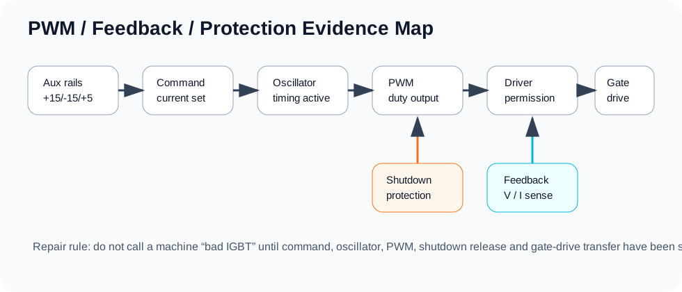
Use this chain in repair records: VCC present → reference present → oscillator present → shutdown released → PWM output present → driver stage receives pulse → gate branches are symmetric → real current is confirmed under staged power-up.
PWM, feedback and protection evidence before board replacement
For no-output and current-not-adjustable faults, separate the command signal, oscillator, PWM output, shutdown/protection state and gate-drive transfer before replacing the main board or IGBT module. A fan or display only proves auxiliary power; it does not prove PWM permission.
Use this chain in repair records: VCC present → reference present → oscillator present → shutdown released → PWM output present → driver stage receives pulse → gate branches are symmetric → real current is confirmed under staged power-up.