ZX7 series
ZX7-315 / 400 / 500 / 630 IGBT Inverter Welder Repair Notes
Repair reference for large ZX7 IGBT inverter welders, covering power stage structure, front-panel functions, protection indicators, PCB boards, common faults and rating-dependent components.
Repair scope covered by this ZX7 series reference
This page covers the board-level repair pattern used by large three-phase ZX7 IGBT inverter welders in the 315A, 400A, 500A and 630A range. These machines are built around a high-voltage rectifier stage, DC bus capacitors, paired IGBT power modules, a main transformer, fast-recovery output rectifiers, a current sensor and several control transformers feeding the control and drive boards. In the field, the model number can change while the service logic remains similar: confirm input power, confirm auxiliary and control supply, identify protection state, then separate the main power stage from PCB-level causes before replacing expensive modules.
The important practical point is that a visible indicator is only the start of diagnosis. A fan that runs abnormally, a blank front display, an undervoltage lamp, an overcurrent lamp or an unresponsive current knob each points to a different branch of the machine. Treating every symptom as a bad IGBT wastes parts. Treating every symptom as a bad control board can also miss a phase-loss input problem, a failed fan, a weak supply circuit or a shorted fast-recovery diode module.
Simplified machine architecture
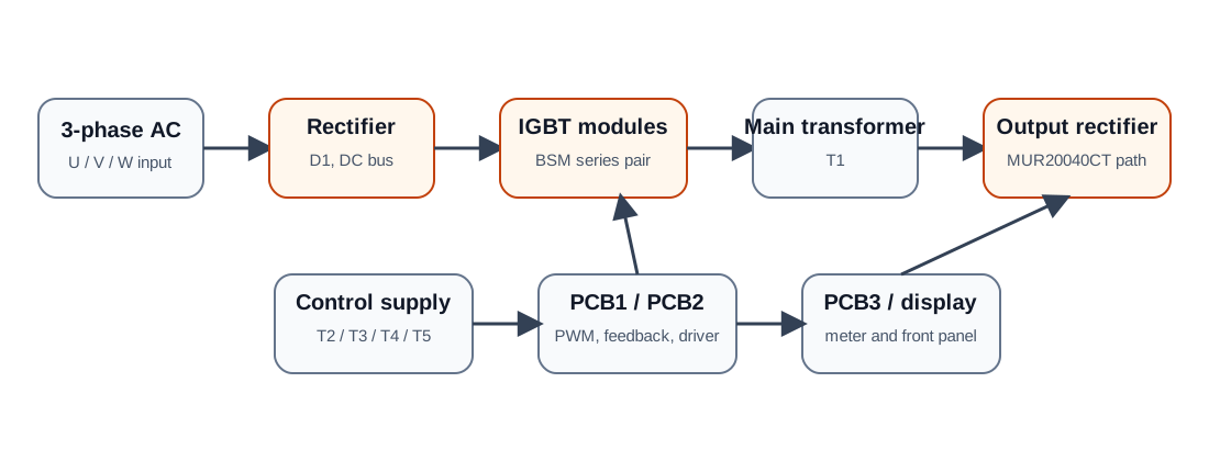
The service manual identifies the main transformer, reactor, several control transformers, filter capacitors, rectifier bridge, contactor, current sensor, output terminals, fan, display, panel switches, potentiometers, fast-recovery rectifier devices, IGBT modules and three PCB assemblies. The exact physical layout varies between current ratings, but the technician should keep the functional map in mind: high-energy power conversion on one side, low-voltage sensing and control on the other, and a driver interface between them.
| Section | Typical parts or signals | Repair relevance |
|---|---|---|
| Input and DC bus | U/V/W input, D1 rectifier bridge, C5-C6 filter capacitors, contactor MS | Phase loss, weak input supply, burned rectifier, bus short, precharge or contactor faults. |
| Power inverter | IGBT1, IGBT2, BSM75GB120 to BSM200GB120 series modules depending on rating | Shorted module, repeated module failure, gate-drive imbalance, overcurrent protection. |
| Output stage | Main transformer T1, reactor L1, MUR20040CT fast-recovery rectifier path | No output, shorted output diode, unstable arc, excessive current stress. |
| Control and display | PCB1 FHP2701, PCB2 FHP2001, PCB3 FHP2005, UP5135 display, RP1/RP2/RP3 | No display, current cannot adjust, false protection, feedback error, missing PWM. |
Front-panel functions that affect diagnosis
The front panel is not just user interface hardware. Welding current, arc-force current and hot-start current are all service clues. If the current display responds to RP1 but the machine has no output, the control board may still be partially alive and the fault may sit in the driver, power stage, output rectifier or protection path. If the display is blank, the technician should first check control supply, panel wiring, phase presence and protective fusing instead of immediately checking the IGBT module.
The output-cable length switch is also important. In normal service the switch should remain in the standard position. When long welding leads are used, the extended-cable position compensates for the changed output condition. If a short lead is used while the switch remains in the extended position, the arc may become harsh and spatter can increase. This is not necessarily a board failure; it can be a setting error.
Polarity matters as well. Basic electrodes are normally used with reverse polarity, with the electrode holder on the positive output. Acid electrodes are normally used with straight polarity, with the electrode holder on the negative output. Wrong polarity will not usually create a PCB fault, but it can create complaints that resemble poor current control or unstable welding.
Common symptoms and first checks
| Symptom | Likely first branch | Recommended first check |
|---|---|---|
| Power switch on, fan abnormal | Input wiring, fan wiring, jammed fan or burned fan winding | Inspect supply wiring and fan harness before testing control boards. |
| Power switch on, front panel blank | Control circuit fuse, V/W phase loss or control supply failure | Check the 2A/250V control fuse and all three input phases. |
| Undervoltage indicator on | Low grid voltage, soft input circuit, PCB1 undervoltage section or U-phase loss | Measure line voltage under load and confirm phase presence before replacing PCB1. |
| Overcurrent indicator on | IGBT, fast-recovery diode, driver transformer, PCB1/PCB2/PCB3 | Remove destructive full-power starts; isolate the 540VDC bus and check drive signals. |
| Current cannot be adjusted | Panel potentiometer or PCB1 feedback/given-current section | Verify RP1 wiring and the PCB1 current-feedback path. |
Rating-dependent components
Large ZX7 machines share the same diagnostic logic but scale several components with current rating. The service data lists 1000µF/400V filter capacitors, a 100A/1200V or 150A/1200V rectifier bridge, CHB-300S or CHB-500S current sensors, output connectors sized around DKJ70-1 or DKJ95-1, and BSM series IGBT modules that scale from BSM75GB120 through BSM200GB120. For repair, the component type is not just a parts-ordering detail. It tells the technician how much current stress the board was designed to handle and whether a substitution is electrically plausible.
| Model family | IGBT reference | Current sensor reference | Notes |
|---|---|---|---|
| ZX7-315 | BSM75GB120 | CHB-300S class | Lower current version, still uses the same protection logic. |
| ZX7-400 | BSM100GB120 | CHB-300S class | Common service platform for medium industrial MMA use. |
| ZX7-500 | BSM150GB120 | CHB-500S class | Higher output current, more sensitive to cooling and output rectifier condition. |
| ZX7-630 | BSM200GB120 | CHB-500S class | Highest current version in this reference; verify output connectors and thermal path carefully. |
How to classify a fault before board removal
A useful repair workflow starts before the welder is opened. If the fan is silent or abnormal, check the input and fan circuit. If the front display is blank, check phase presence, the control fuse and low-voltage supply. If the undervoltage lamp is on, confirm the supply under load before removing PCB1. If the overcurrent lamp is on, stop repeated starts and test the power semiconductors. If current adjustment is the only complaint, stay in the panel-control and feedback loop first.
This symptom sorting prevents unnecessary damage. A shorted IGBT can destroy a driver board, but a bad driver board can also destroy a new IGBT. A phase-loss fault can look like a board failure, and a weak workshop supply can make the undervoltage circuit behave exactly as designed. The first job is to decide whether the symptom belongs to the input side, control supply, protection logic, power inverter, output rectifier or feedback loop.
Field notes for replacing high-current parts
When replacing IGBT modules or fast-recovery rectifiers, match the current rating and voltage class rather than copying only the package shape. Check gate resistors, snubber components, transformer primary condition, secondary rectifier condition and cooling contact before powering the machine. A module that failed from bad drive or bad output rectification will often fail again if only the visible shorted part is replaced.
For ZX7-500 and ZX7-630 machines, thermal management becomes more important. Clean heatsink surfaces, proper insulation sheets, correct torque, intact fan airflow and undamaged temperature sensors are part of the repair, not cosmetic details. High-current welders may run for a few minutes after a poor repair and then fail under real duty cycle.
IGBT-ZX7-400 repair note
For 400A-class IGBT ZX7 machines, a repair record should separate the visible power-device failure from the cause that produced it. Record the input short evidence, output rectifier state, gate-drive branch comparison, auxiliary rails, feedback path and restart stage. This keeps the repair path aligned with the WelderData symptom → measurement → workflow model.
When a large ZX7-style machine needs soft-switching checks
Not every ZX7-labeled machine uses the same power topology. Some machines are closer to hard-switching inverter structures, while larger or more advanced units may include soft-switching, resonant or phase-shift full-bridge behavior. The repair path changes when the inverter depends on commutation capacitors, leakage inductance, saturable inductors and current-mode timing.
| Repair clue | Why it matters | Related WelderData path |
|---|---|---|
| Repeated IGBT failure after apparently normal gate-drive checks. | The gate driver may be present while the bridge is losing its soft-switching condition. | IGBT / MOSFET keeps blowing |
| Machine fails during arc start or light-load testing rather than at full current. | No-load and light-load regions can be difficult for soft-switching commutation. | Soft-switching main loop |
| Snubber or resonant capacitors were replaced before the failure repeated. | Incorrect capacitance, pulse rating or pairing can change bridge transition timing. | IGBT precheck tool |
| Transformer primary wiring, busbar routing or saturable inductor was disturbed. | The primary loop is part of the commutation system, not just a power connection. | Soft-switching main loop |
PCB test points and major service references
The ZX7-315/400/500/630 service family includes a TP1-TP16 PCB table and model-dependent current calibration values. The most important shared rails are TP12 +15V, TP13 -15V and TP14 +5V. Rating-dependent values include TP3, TP4 and TP16, so a 315A board should not be adjusted as if it were a 630A board.
| Service item | Reference from the service family | Repair meaning |
|---|---|---|
| Input / rectifier | 3-phase 380V family, large bridge rectifier and DC bus capacitors | Confirm phase presence and DC-bus integrity before low-voltage board replacement. |
| IGBT modules | BSM75GB120 to BSM200GB120 class across the rating range | Match current rating and inspect driver/snubber cause before installing replacements. |
| Output rectifier | MUR20040CT / fast-recovery diode path in the reference platform | A shorted output rectifier can trip protection or destroy the inverter stage. |
| Current detection | CHB-300S / CHB-500S class current sensor references | Feedback evidence must match the machine current class. |
Use the TP1-TP16 calibration workflow before final board adjustment.